
Beam side formwork is one of the most easily underestimated parts of an aluminum formwork system. Wall and column formwork is judged mainly by verticality, while slab formwork is checked for elevation and flatness. Beam side formwork, however, is affected simultaneously by beam depth, width and span, beam-column and beam-wall junctions, changes in slab thickness, downstand beams, upstand beams, lintels over openings and construction loads. If its position or reinforcement is inadequate, the stripped concrete may show bulging beam sides, offsets along beam edges, grout leakage at the soffit, bowed side lines or uneven slab-to-beam junctions.
Changes in beam depth are a central challenge in beam side formwork installation. On a typical floor, the same grid line may include conventional beams, downstand beams, transfer edge beams, lintels, edge beams beside sunken bathroom slabs and balcony cantilever beams. Unless the detailed layout, special-size panels and waler connections are resolved in advance, site crews often resort to infill pieces, omit pins or pack gaps with timber. The resulting dimensional errors and surface defects are then cast permanently into the concrete.
Beam side formwork quality is not simply a question of whether the panels feel secure. Site inspections should cover the beam cross-section, straightness of the beam edge, verticality of the sides, soffit elevation, alignment at slab-to-beam junctions, definition of internal and external corners, joint tightness and stability of the reinforcement system. Once a beam side bulges or develops an offset, the consequences can extend to plastering, suspended ceilings, door and window openings, MEP services and the finished clear height.
In an aluminum formwork system, beam side panels are normally erected together with the beam soffit panels, slab formwork, wall and column panels, and the early-striking support system. They control the structural section and form a critical connection between walls, columns and slabs. Treating them as ordinary side panels can lead crews to overlook changes in beam depth, load transfer at junctions and fresh-concrete pressure.
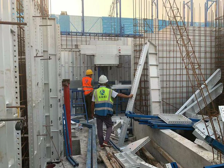
A change in beam depth alters the panel height, connection-hole positions, waler elevations, support points and the interface between the beam and slab. Standard beams can use repeatable panels for fast cycling, but variable-depth beams, downstand beams, transfer beams, edge beams and locally strengthened beams usually require special-size panels. If these changes are not clearly shown in the detailed drawings, crews may find that a panel will not fit, that its holes do not align after installation, or that the level difference between the beam side and slab deck is wrong.
Depth transitions also tend to coincide with congested reinforcement, complex beam-column junctions, reserved openings or MEP sleeves passing through beams. The formwork may need to accommodate these items without sacrificing cross-sectional accuracy or weakening the reinforcement system. Such details should be developed first, trial-assembled second and installed only after verification. Cutting or modifying aluminum panels on site should be avoided.
| Type of beam-depth change | Typical location | Key formwork controls |
|---|---|---|
| Conventional beam changing to a downstand beam | Living rooms, corridors and edges of equipment platforms | Special-size beam side panel height, soffit elevation and straightness of the slab-beam internal corner. |
| Edge beam or balcony cantilever beam | Facades, balconies and areas near bay windows | External lines, relationship to upstands, support and edge protection reinforcement. |
| Transfer beam or strengthened beam | Transfer floors and local long-span areas | High side pressure; waler and tie details require a dedicated check. |
| Lintel or coupling beam over an opening | Door and window openings, service shafts and stairwells | Opening dimensions, level soffit, corner joints and clashes with reinforcement. |
| Edge beam beside a sunken slab | Bathrooms, kitchens and balconies | Changes in slab thickness, suspended kicker/upstand details and grout control at the bottom joint. |
Smooth beam side installation starts with sound formwork detailing. During this stage, the layout should be divided according to beam depth, beam width, span, slab thickness, beam soffit elevation, beam-column junctions, beam-wall junctions and non-typical floors. Standard beam side panels improve cycle efficiency, but depth transitions require dedicated special-size panels, adapter panels or compensation panels. Temporary site materials should not be relied on to close the gaps.
The CIEZN Formwork aluminum formwork panel system includes both standard and special-size panels. Its connection system uses wedges and pins to maintain continuity, while square or rectangular hollow-section walers control dimensional accuracy. For beam sides, this means that panel heights, hole positions, waler lines, support points and connections to the slab formwork must all be arranged in the detailed drawings.
Beam side panels should not simply be assembled from one end to the other according to crew habit. A more dependable sequence is to verify the beam soffit elevation and beam edge lines first, install the soffit formwork and support system, erect the beam side panels, and finally close them against the slab, wall and column panels before carrying out a coordinated alignment check. Fixing the beam sides too early can pull them out of position when the slab or wall and column formwork is later adjusted.
Pay particular attention to beam ends, beam-column junctions, beam-wall junctions, intersecting beams and corners of downstand beams. The internal corner between the beam side and soffit must be tight, and the top edge of the beam side must close smoothly against the slab formwork. An uneven top edge commonly produces offsets at slab-to-beam junctions after casting, and these are labor-intensive to repair.
| Installation step | Control point | Common problem |
|---|---|---|
| Position the beam soffit | Verify soffit elevation, beam width and prop locations | Soffit deflection or incorrect beam depth. |
| Place beam side panels | Install by panel number and check orientation and hole positions | Special-size panels mixed up or misaligned at depth changes. |
| Close the junctions | Fit beam sides tightly to wall, column, slab and soffit panels | Grout leakage at internal corners and offsets at slab-beam junctions. |
| Secure connections | Install all pins and wedges with holes aligned | Loose joints and outward bulging during concrete placement. |
| Align the complete run | Recheck beam edge lines, verticality and straightness of the top edge together | Individual points pass inspection while the overall line remains bowed. |
The governing principle at a beam-depth transition is clarity of section, interface and load path. A clear section means that beam depth, beam width, slab thickness, soffit elevation and the finished levels are unambiguous. A clear interface means that transitions, stop ends, and internal and external corners between panels of different heights use dedicated components. A clear load path means that walers, ties and supports transfer fresh-concrete pressure into a stable system.
Packing a depth transition with small timber pieces, scrap aluminum or mortar is one of the least reliable site solutions. It may seem quicker, but it frequently causes grout loss, offsets, dimensional errors and poor appearance after striking. The proper approach is to detail stepped panels, stop-end panels, corner panels or compensation panels in advance and confirm closure through trial assembly before installation.
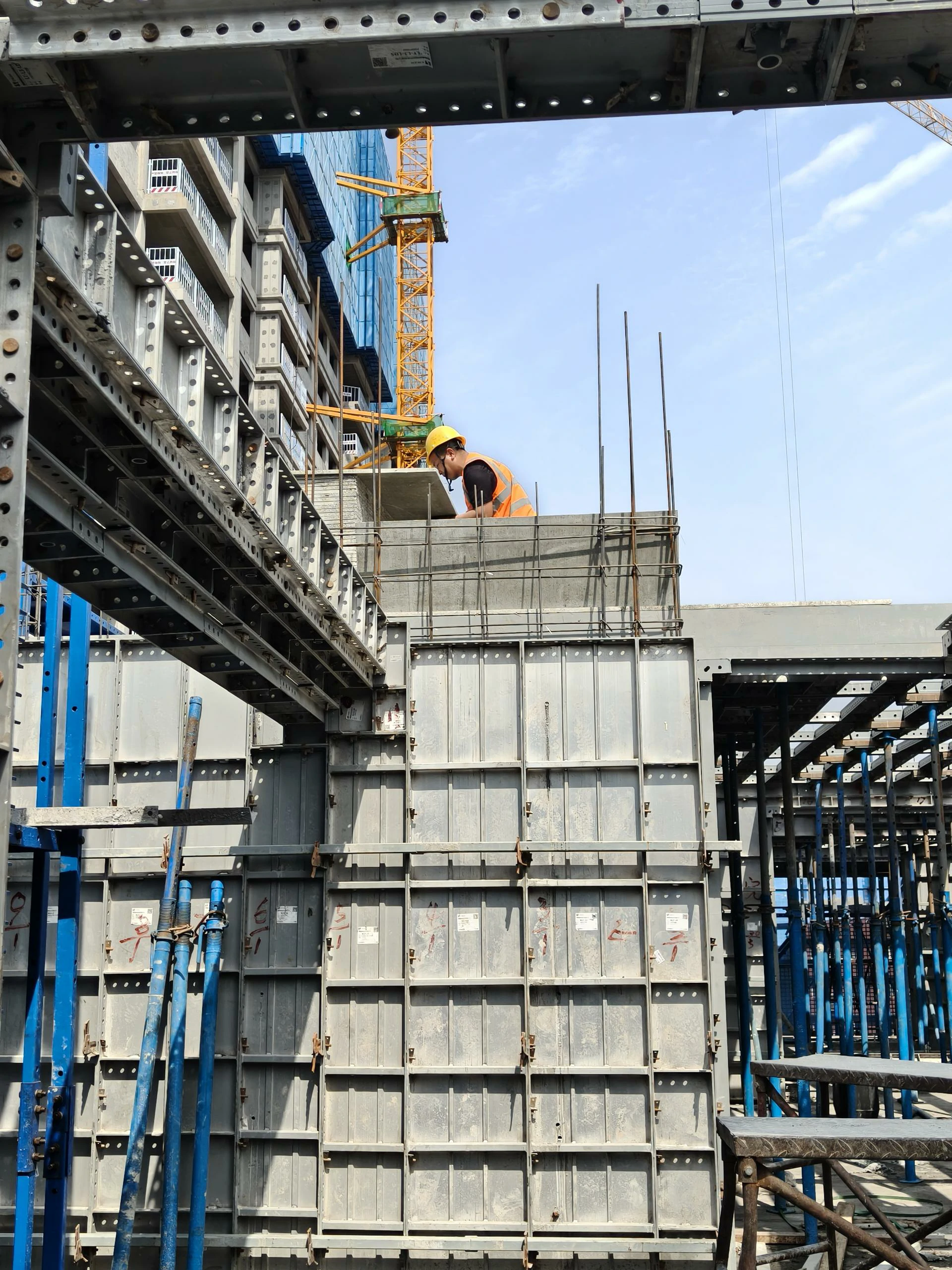
Beam side reinforcement cannot depend on panel stiffness alone. During placement, the sides are subjected to fresh-concrete pressure, vibration and construction loads. On conventional beams, deformation can be controlled with correctly spaced pins and wedges, walers and supports. Deep beams, edge beams and transfer beams require a higher level of reinforcement, potentially including closer waler spacing, through-ties or purpose-designed bracing.
CIEZN wedge pins can work with a tie system to secure the panels, while flat ties control formwork spacing. On site, these aluminum formwork accessories keep the assembly closed and dimensionally stable. For beam sides, every pin and wedge must be installed in its designated hole, walers must restrain areas prone to outward bulging, and ties or braces must transfer local pressure into stable supporting members.
| Reinforcement component | Function on beam sides | Inspection focus |
|---|---|---|
| Pins and wedges | Connect adjacent panels and keep joints closed | No missing or reversed components; wedges must be fully locked, not merely inserted. |
| Walers / hollow sections | Control outward bulging and maintain a straight beam edge | Elevation, spacing, continuity and end restraint must follow the approved scheme. |
| Flat ties / through-ties | Limit panel spacing and lateral deformation | Avoid clashes with reinforcement and ensure the connection cannot loosen. |
| Steel props | Support the beam soffit and slab deck and stabilize the overall system | Props must be plumb; adjustable-head extension, sole-level bracing and horizontal bracing must comply with the scheme. |
| Push-pull props / temporary restraints | Control lateral movement at edge beams, cantilevers and junctions | Use reliable fixing points and recheck before casting. |
The locations most likely to fail are usually not at midspan, but at beam-column junctions, beam-wall junctions, intersecting beams and slab-to-beam interfaces. Reinforcement is congested, panel corners are numerous and connection holes may be difficult to access. To make installation easier, crews may be tempted to reduce the number of connections or relax joint-tightness requirements.
At a beam-column junction, the geometry between the column head panels, beam sides and beam soffit must be accurate. At a beam-wall junction, wall walers and beam-side walers require proper clearance and overlap. At a slab-to-beam junction, the slab deck elevation and beam-side top edge must align smoothly. Unless these details are corrected as a complete assembly, individual panels may appear acceptable while the stripped concrete line remains uneven.
Reinforcement is often more congested where beam depth changes, especially at beam-column junctions, transfer beams, cantilever beams and coupling beams over openings. Main bars, stirrups, closely spaced confinement steel, reserved MEP sleeves and embedded items can prevent the formwork from closing, open the joints or push a beam side panel out of line.
Before closing the formwork, check beam reinforcement cover, the outer dimensions of the stirrups, reserved openings and MEP sleeve elevations. Reinforcing steel must not bear directly against an aluminum panel, and cover blocks must be stable. Embedded items must not occupy pin holes, waler positions or beam-side adapter panels. For deep beams and complex junctions, the technical team, reinforcement crew and aluminum formwork crew should carry out a joint inspection.
A correctly installed beam side is not automatically a correctly cast beam. Fresh-concrete pressure is more pronounced in deep beams, while holding a poker vibrator against a side panel for too long increases the risk of movement. Control the discharge height, lift thickness and vibration time. Beam-column and beam-wall junctions must be fully compacted without over-vibration.
The formwork watch should focus on beam-side top edges, soffit internal corners, stop ends, waler connections, loose wedges and the support system. If a beam side begins to bulge, a joint leaks grout, a support settles or a junction moves, stop placing concrete locally and correct the problem at once. The earlier a problem is detected, the lower the repair cost.
After stripping the beam sides, promptly inspect the beam cross-section, soffit elevation, side verticality, edge straightness, offsets at slab-to-beam junctions, internal and external corners, and overall finish. Record depth transitions separately because they are most prone to systematic errors. If defects appear on the benchmark floor, trace them back to the detailed drawings, special-panel numbering, waler positions and installation sequence.
Do not pry aggressively at beam-side corners or soffit internal corners during striking. Clean residual mortar from removed panels and check edge ribs for deformation, holes for wear, welds for cracking and panel faces for dents or high spots. Deep-beam, downstand-beam and special-size side panels should have a reuse and maintenance checklist so that the same defect is not repeated on the next floor.
| Inspection item | What to check | Where to trace the cause |
|---|---|---|
| Beam cross-section | Whether beam depth and width match the detailed drawings | Special-panel height, setting-out lines and waler-induced bulging. |
| Beam soffit elevation | Whether the soffit has deflected or developed a local offset | Support system, adjustable heads and soffit-panel installation. |
| Beam-side verticality | Whether the beam is leaning or twisted | Push-pull props, walers, ties and fresh-concrete pressure. |
| Slab-to-beam junction | Whether the top edge is smooth and the internal corner is free from grout loss | Beam-side top edge, slab-deck elevation and joint closure. |
| Surface finish | Honeycombing, bugholes, damaged arrises and grout marks | Joints, vibration, stripping and panel cleaning. |
| Quality issue | Possible cause | Recommended action |
|---|---|---|
| Bulging beam side | Waler spacing too wide, loose wedges or excessive placement rate | Strengthen the reinforcement details and recheck connectors and walers before casting. |
| Incorrect beam depth | Special-size panels mixed up, wrong soffit elevation or unchecked detailing dimensions | Manage panels by beam-depth number; remeasure the benchmark floor and correct the detailing. |
| Offset at slab-to-beam junction | Beam-side top edge does not match the slab-deck elevation | Align beam sides, soffit and slab deck together, then perform a second check before casting. |
| Grout leakage at soffit internal corner | Loose beam-side-to-soffit joint or inadequate corner closure | Repair panel edge ribs, install all connectors and seal the joint as specified where necessary. |
| Beam end out of square | Beam-column junction not fully closed or reinforcement/embedded items pushing against the panel | Jointly inspect reinforcement cover and junction panels before closing the formwork. |
| Bowed line after stripping | Insufficient overall alignment or discontinuous walers | Check the full run against grid and edge lines, and secure waler ends reliably. |
The most vulnerable areas are beam-depth transitions, beam-column and beam-wall junctions, slab-to-beam interfaces, edge beams and transfer beams. These locations involve multiple panel transitions, congested reinforcement and complex load paths, so they require focused inspection.
Improvised infill should not be treated as a standard solution. Dedicated special-size panels, adapter panels or stop-end panels should be provided during detailing. Makeshift infill is prone to grout leakage, offsets and cross-sectional errors.
Control comes from pins and wedges, walers, flat ties or through-ties, beam soffit supports and push-pull props working together. For deep beams, fresh-concrete pressure and reinforcement spacing should also be checked against a project-specific scheme.
Typical causes include fresh-concrete pressure, vibration, excessive waler spacing, loose connectors or settlement of the supporting system. Reinforcement details must be rechecked before casting, and a dedicated formwork watch is also required during placement.
A supplier can reduce installation risk through detailed panel layouts, fabrication of special-size panels, trial-assembly numbering, reinforcement-detail recommendations and site briefings. The project team should provide complete structural information and promptly report measured results from the benchmark floor.
The main difficulties in beam side aluminum formwork lie in changes in beam depth, complete closure at junctions and the reinforcement system. Depth changes must be resolved through detailed panel layouts and special-size formwork. Junction closure depends on the installation sequence and joint control, while the reinforcement system relies on pins and wedges, walers, ties and supports working together. Simplifying any one of these stages can result in bulging sides, offsets along beam edges or uneven slab-to-beam junctions after casting.
For main contractors, aluminum formwork subcontractors and procurement teams, beam side formwork should not be assessed only by panel area and delivery time. Site productivity depends heavily on a supplier's detailing capability, experience with junctions, accessory configuration and benchmark-floor service. Accurate beam-side details allow the one-pour advantage of aluminum formwork to deliver measurable benefits in structural dimensions, concrete finish and downstream finishing costs. CIEZN also provides formwork engineering services and project support; project-specific requirements can be discussed through its contact page.
Phone: +8618711321769
Email: alame.vicky@gmail.com
WhatsApp: +8615400055585
Address:No.88, Shuntian Avenue, Xiangyin District, Xiangjiang New District Hunan Province

 EN
EN
 RU
RU
 AR
AR
 ES
ES