
In an aluminum formwork system, large wall panels are relatively straightforward to install. The real test of workmanship is often at the corners. Internal and external corner panels may account for only a small number of components, but they directly determine whether wall corners are square, corner lines are straight, joints remain grout-tight, and beam-wall junctions, door and window openings, stairwells, bay windows and lift shafts achieve a consistent finish.
Poor control at either an internal or external corner rarely remains a local defect. Common results after stripping include offsets in the wall face, displaced corners, bowed internal corners, chipped external arrises, excessive diagonal variation and difficult interfaces with later masonry or finishes.
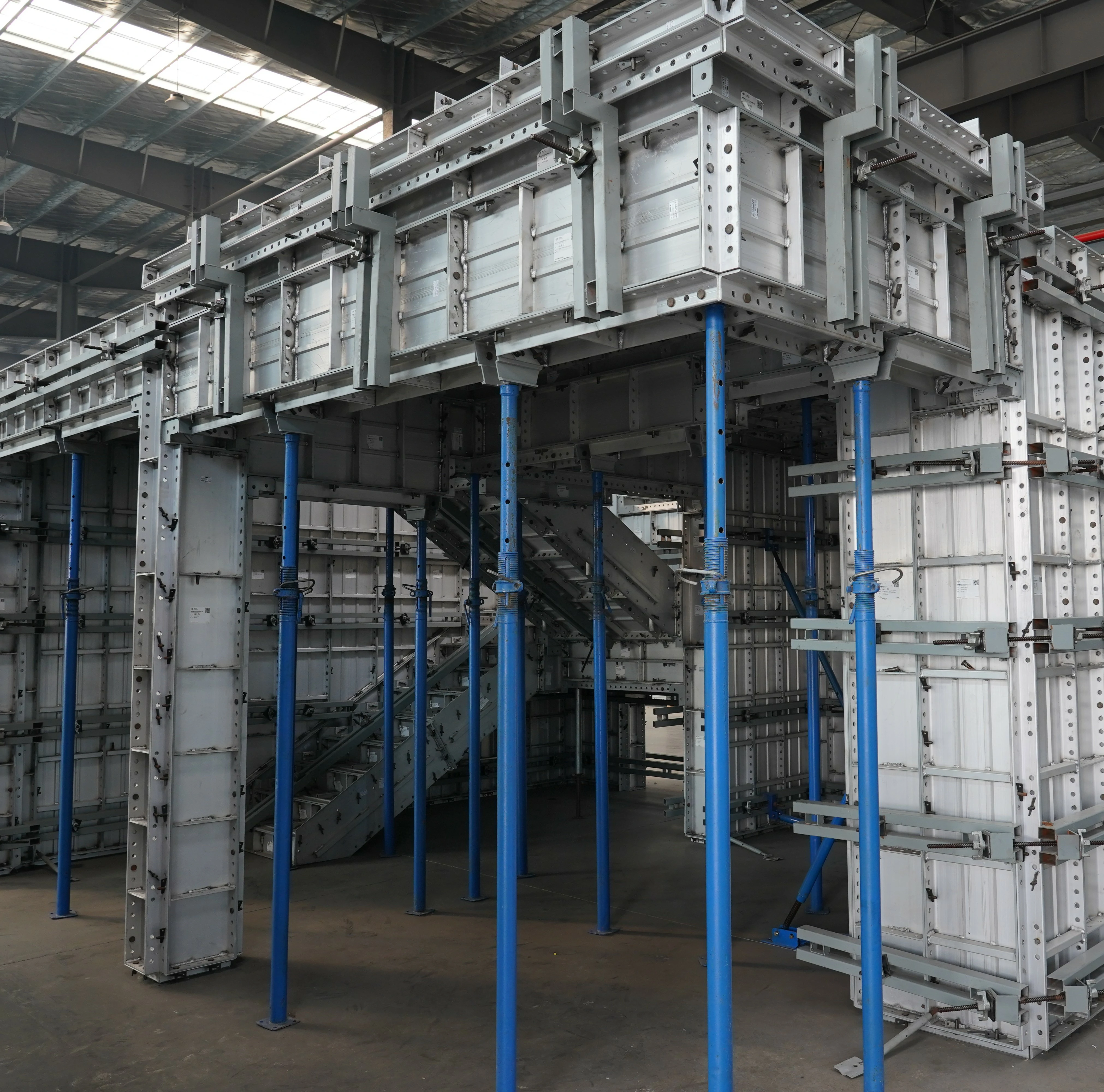
Internal corner panels are used where two walls meet internally and at internal wall-to-beam, wall-to-slab or wall-to-column junctions. They control the verticality and straightness of the internal corner and close the connecting joint. External corner panels are used at outside wall corners, column corners, outside edges of door and window openings and external bay-window edges. They control the outside line, corner squareness and the appearance of the finished concrete.
From a construction-control perspective, the internal corner panel closes the inside angle and coordinates intersecting walls, while the external corner panel forms the outside angle and protects the arris. Neither works in isolation. Both must operate with standard and special-size wall panels, walers, pins and wedges, and flat-tie or through-tie systems to control corner quality.
Corners concentrate changes in both formwork loading and joint arrangement. Large wall panels are relatively regular, whereas a corner may combine changes in wall thickness, door or window openings, concealed structural columns, beam-to-slab interfaces, stair landings, upstands and MEP reservations. If any one condition is not properly resolved, the corner can move, develop an offset or leak grout.
The issue is often not inadequate panel strength by itself. More common causes include incomplete detailing, a corner panel installed in the wrong orientation, omitted pins or wedges, walers terminating at the corner, unchecked wall diagonals, or reinforcement and embedded items pushing the corner panel out of position. Once the corner moves, the squareness error is amplified along both adjoining walls.
| Source of problem | Typical symptom | Downstream effect |
|---|---|---|
| Unclear panel layout | Corner and wall-panel holes do not align, or special panels are mixed up | Site rework, makeshift infill and enlarged joints. |
| Insufficient connections | Loose corners and locally open joints | Grout leakage and corner bulging during placement. |
| Interrupted reinforcement | Walers or ties stop at the corner | Loss of wall squareness and displaced corners. |
| Incorrect setting out | Wall edge lines do not close and diagonals differ excessively | Out-of-square walls and difficult finishing interfaces. |
| Rough stripping | Chipped external corners and damaged arrises | Extensive repair and poor appearance. |
Successful corner installation starts with detailed design. The drawings should define wall thickness and length, corner type and panel size, wall-panel layout, connection holes, waler positions and interfaces with beams, slabs, openings, upstands and stairs. Reusable corner panels on typical floors should be standardized wherever possible. Non-typical floors and special junctions require dedicated special-size corner panels or adapter panels.
CIEZN Formwork panels can be customized to project drawings and connected into an integrated load-bearing assembly with connectors and reinforcement walers. At a corner, the decisive issue is not the corner panel alone, but how it matches adjacent wall panels, beam side panels and opening panels. Makeshift correction at the workface rarely delivers consistent formed quality.
Wall corners cannot be aligned reliably by experience alone. Before installation, verify grid lines, wall face lines, wall-thickness lines, corner control lines and diagonals. Where necessary, pull a continuous line along long walls and walls with multiple returns to identify accumulated error. Whether an internal or external corner is square ultimately depends on the accurate position of both adjoining walls.
A useful site method combines edge-line and diagonal checks. First confirm the dimensions and intersection of the two wall face lines, then measure the diagonals across key rectangular areas, and finally check the corner point against the structural grid. High-accuracy locations such as lift shafts, stairwells, cores, bathrooms and external wall corners should be measured both before and after formwork installation.
| Setting-out item | Checking method | Control purpose |
|---|---|---|
| Wall face lines | Verify the dimensions and intersection of both wall faces | Position the corner accurately. |
| Wall-thickness lines | Measure the clear distance between opposite panels | Prevent wall-thickness errors and local inward or outward movement. |
| Diagonals | Spot-check rectangular zones or room diagonals | Determine wall and room squareness. |
| Vertical control line | Check together with push-pull props and walers | Keep the corner plumb and aligned through its full height. |
| Level line | Check the corner elevation against beam and slab junctions | Prevent offsets at wall-to-beam interfaces. |
When installing an internal corner panel, the priority is to close the two intersecting wall panels tightly at the inside angle and establish a plumb internal corner line. Normally, the wall face lines and thickness should be checked first, followed by installation of the internal corner panel, which then guides the adjacent wall panels into closure. If both large wall runs are locked first and the corner panel is forced into the remaining space, the holes may not align, edge ribs may clash and the internal joint may open.
Immediately after installation, check internal-corner verticality, joint width and the flatness of the adjoining wall panels. Internal corners are particularly prone to grout loss, so every pin and wedge must be installed in the correct hole. Joint-sealing or foam strips may be added where specified by the project. Once cement paste enters an open corner joint, it affects the finish and increases resistance during stripping.
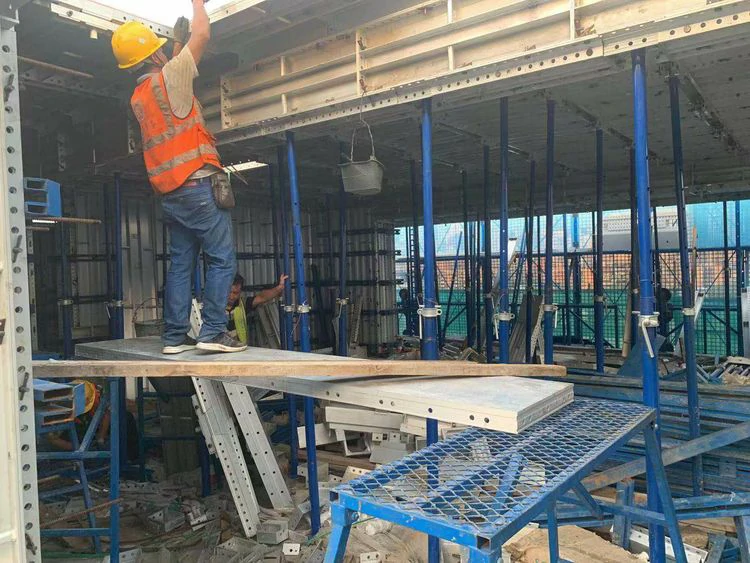
External corner panel installation must keep the outside line straight, the angle square and the arris stable enough to remain intact after stripping. A leaning outside corner is immediately visible and difficult to hide with later repairs. Establish the external corner reference line first, then close and secure the wall panels on both sides against the corner panel.
Damaged external corner panels should not remain in the reuse cycle. Dented edge ribs, a rounded outer edge or worn holes commonly produce soft-looking corners, chipped arrises and offsets after stripping. At door and window openings, bay windows and balcony corners, the external corner panel must also be coordinated with opening panels, edge-beam panels and drip details rather than checked only against plan dimensions.
Corner-joint control depends on close-fitting edge ribs, complete connections and a continuous load path. A joint does not need to be forced as tight as possible; it needs to be even, straight and lockable while the panels remain geometrically correct. If a panel is deformed, driving wedges harder may close one local gap while leaving the overall corner line twisted.
When correcting a corner joint, first check panel compatibility and hole alignment, then reinforcement and load transfer, and only then consider sealing materials. Heavy reliance on packing or sealant usually indicates a problem with detailing or installation sequence. At corners, panel fit and wall squareness take priority over cosmetic joint filling.
| Joint location | Main control | Common risk |
|---|---|---|
| Internal corner joint | Close-fitting ribs, aligned holes and a straight inside line | Grout leakage, trapped debris and poorly defined internal corners. |
| External corner joint | Straight outside line and close-fitting panels on both sides | Offsets, chipped arrises and weak-looking lines. |
| Wall panel to corner panel | Aligned holes and complete connections | Local opening and bulging during casting. |
| Wall-to-beam corner | Matching vertical elevation and horizontal line | Offsets at internal or external wall-beam corners. |
| Opening corner | Corner and opening panels aligned together | Dimensional errors and grout leakage around doors or windows. |
Wall squareness is not merely a result checked after stripping; control starts during installation. In enclosed rooms, cores, lift shafts, bathrooms, plant rooms and areas with numerous openings, use wall-edge dimensions, clear room dimensions, diagonals and vertical lines together.
Do not focus on a single corner in isolation. Many corner errors originate as accumulated deviation along a long wall and become visible only at the return. Treat the corner panel as a locking point in the overall wall alignment, using it to guide both walls straight rather than forcing the corner after the walls have moved. If diagonal variation exceeds the permitted range, investigate the setting out, push-pull props, walers and panel numbering.
Although corner panels have a small surface area, their reinforcement must not be reduced. Corners redirect fresh-concrete pressure and carry complex loads, so walers, flat ties, through-ties, push-pull props and supports must not terminate arbitrarily. CIEZN Formwork uses wedge and pin connectors together with walers to secure the formwork as an integrated assembly. At corners, the local panel must be included in the load path of the entire wall.
Insufficient reinforcement at a corner commonly leads to bulging, out-of-square walls and opened joints during placement. Check waler continuity across the corner, fixing points for corner props, tie locations that avoid reinforcement clashes, and stable wall-thickness control. Even a straight-looking corner will produce incorrect room dimensions if wall thickness is lost at the junction.
| Reinforcement component | Function | Inspection focus |
|---|---|---|
| Walers | Maintain wall straightness and restrain corner bulging | Confirm continuity or a reliable connection at the corner. |
| Pins and wedges | Lock corner panels to adjoining wall panels | Confirm every connector is installed, locked and correctly oriented. |
| Flat ties / through-ties | Control wall thickness and lateral deformation | Check suitable positions near the corner and ensure none are omitted. |
| Push-pull props | Control verticality and corner position | Use reliable fixing points and ensure adjustment remains locked. |
| Support base | Prevent overall settlement from destabilizing the corner | Provide a firm bearing surface with no settlement. |
Correct installation does not by itself guarantee a satisfactory finished corner. Concentrated discharge, repeated vibrator contact with the corner panel or an inadequate formwork watch can still cause movement, grout leakage or bulging. Control placement rate around internal and external corners, avoid one-sided impact, and compact thoroughly without over-vibration.
During stripping, protect external corners first. Internal corners are generally easier to release, whereas prying against an outside arris can chip it immediately. Inspect corner-panel ribs, welds and holes as soon as panels are removed. Corner panels accumulate reuse damage more readily than ordinary wall panels and deserve a separate inspection and maintenance routine.
| Quality problem | Possible cause | Control measure |
|---|---|---|
| Grout leakage at internal corner | Internal joint not closed, missing wedges or deformed corner panel | Correct panel compatibility and connections first, then seal the joint as specified. |
| Chipped external corner | Damaged panel, rough stripping or insufficient concrete strength | Replace deformed panels and follow the correct stripping sequence and timing. |
| Out-of-square walls | Setting-out error, unchecked diagonals or inadequate corner reinforcement | Remeasure edge lines and diagonals before and after installation and align the assembly as a whole. |
| Offset at corner | Mismatch in corner and wall-panel elevations or poor rib contact | Check panel elevations and compatibility; do not mix panel numbers. |
| Bulging at corner | Interrupted walers, insufficient ties or excessive placement impact | Complete all reinforcement details and control placement rate and sequence. |
| Uneven internal or external corner line | Accumulated long-wall deviation or forced correction at a single point | Align the complete wall against a continuous line and use the corner panel to lock the overall geometry. |
No. Their load directions, edge-rib arrangements and formed objectives differ. Each panel must be used according to its number and intended junction. Mixing them readily causes misaligned joints and dimensional errors.
First check whether the corner and wall panels match, whether holes align and whether all pins and wedges are installed. Then check the walers and reinforcement. Joint-sealing material should be considered only after those items are correct.
No. Diagonals are important, but edge-line dimensions, wall thickness, verticality and alignment through successive floors must also be considered.
An external corner is an exposed line, so deformation, offsets or chipping are immediately visible. It is also more vulnerable during stripping and therefore needs protection during installation, casting and stripping.
A supplier can reduce site rework through detailed panel layouts, dedicated special-size corner panels, trial assembly, junction briefings and connection and reinforcement recommendations. The project team should provide complete drawings and benchmark-floor feedback for the best result.
Internal and external corner panels may be only one part of a corner junction, but they define the boundary quality of the formed wall. Internal corners must close cleanly and remain straight; external corners must form crisp lines while protecting the arris. Corner joints and wall squareness depend on every stage, from detailing and setting out through installation, reinforcement, casting and stripping.
For main contractors, aluminum formwork subcontractors and procurement teams, stable measured quality and a consistent wall finish require more than checking the flatness of large wall panels. Internal and external corners must be treated as key control points. When the panel layout, panel condition, corner reinforcement and squareness checks form a closed process, an aluminum formwork panel system can deliver straighter lines, squarer rooms, less repair and a more consistent finish. CIEZN provides formwork engineering support; project requirements can be discussed through the contact page.
Phone: +8618711321769
Email: alame.vicky@gmail.com
WhatsApp: +8615400055585
Address:No.88, Shuntian Avenue, Xiangyin District, Xiangjiang New District Hunan Province

 EN
EN
 RU
RU
 AR
AR
 ES
ES