
Accurate OEM aluminum formwork pricing requires more than sending a set of building drawings to the factory. The formwork design must translate architectural, structural, MEP, and construction-planning information into wall panels, beam and slab panels, corner forms, props, walers, ties, and accessory schedules. One missing input can lead to misplaced openings, incorrect wall thickness, an excessive proportion of non-standard panels, or even a system that cannot be assembled after production.
When sending an inquiry to an aluminum formwork supplier such as CIEZN TECH, the project team should prepare one coordinated information package and appoint a technical contact as well as a controlled drawing revision. Only after receiving complete information can the supplier assess the formwork scope, standard-panel reuse rate, number of new panels, pre-assembly workload, and lead time. The following checklist can be attached directly to a request for quotation or used as a drawing handover index.
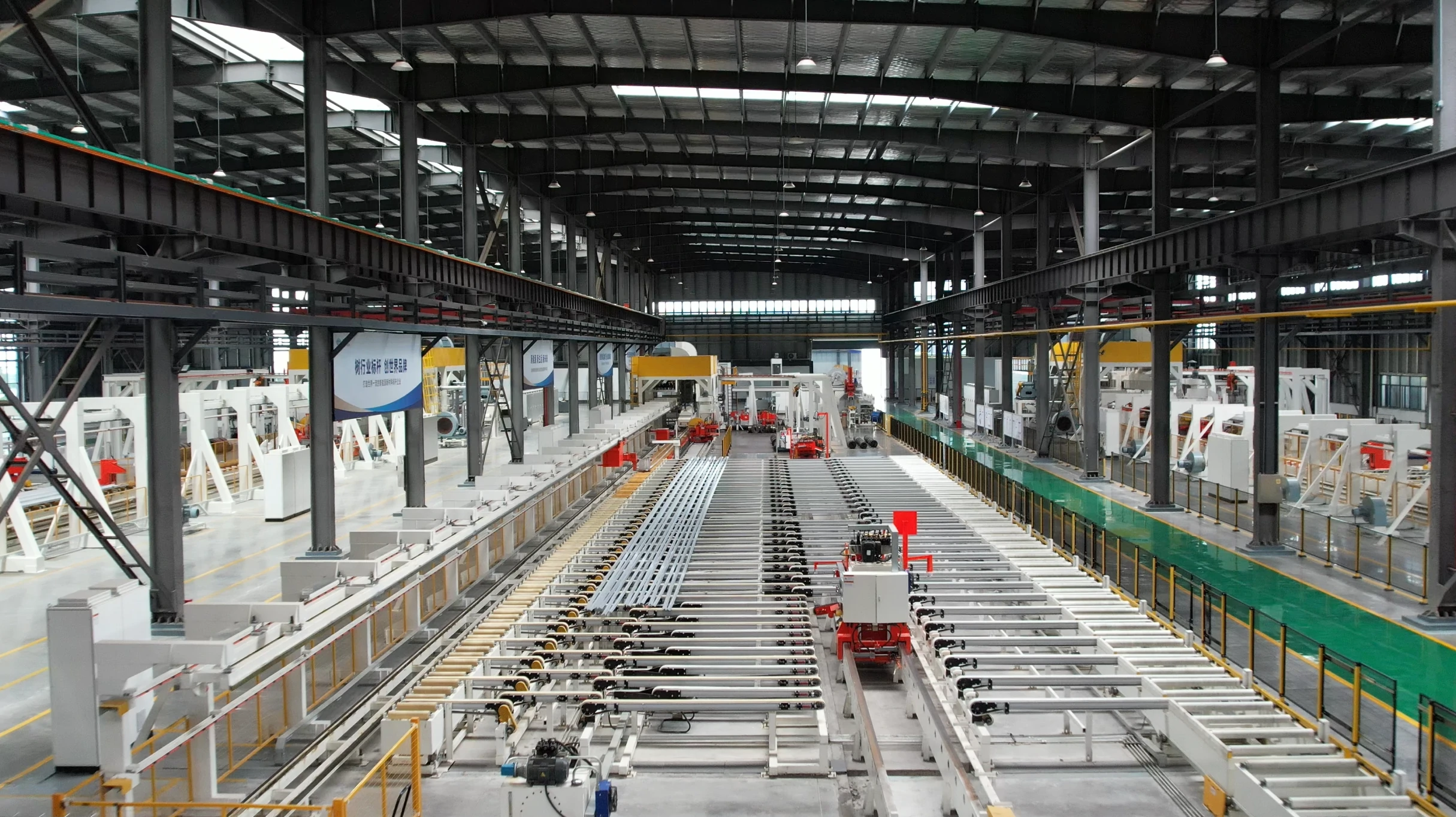
Project conditions outside the drawings directly affect formwork design and packing. Use a one-page sheet to state:
The main contractor's technical and procurement teams should approve this sheet together. If the supply scope has not yet been decided, mark it as “to be confirmed” rather than leaving the supplier to make assumptions. The same information helps buyers choose the right aluminum formwork system.
Architectural drawings define spaces, openings, and formed boundaries. Provide editable DWG files together with stamped or approved PDFs, and make sure both formats carry the same revision. The mandatory package includes:
If the architectural design is still changing frequently, select one typical unit for a trial layout and expand the design to the whole building only after openings and details are frozen. Otherwise, every change to a door, window, or wall pier can trigger linked revisions to several panels and their numbers. This is one reason shop drawings matter in aluminum formwork projects.
Structural drawings define the concrete dimensions that come into direct contact with the formwork, so they must be more complete than the architectural set. The project team should submit:
Architectural and structural dimensions must be cross-checked before detailing begins. If wall thicknesses, openings, beam positions, or levels conflict, the supplier should issue a query list for written response by the project designer or main contractor's technical team. Unconfirmed dimensions must not be released into production drawings.
Once panel holes and waler positions are fixed, adding electrical boxes, sleeves, or openings later will require panel modification. At a minimum, the MEP package should cover:
The MEP contractor should sign directly on the aluminum formwork shop drawings rather than issue a separate coordinate schedule. For openings that have not been frozen, establish one post-installation treatment rule and define which holes may be made on site and which must be prefabricated at the factory.
OEM supply does not always mean manufacturing every panel from new material. If the project plans to reuse old aluminum formwork through secondary design, provide a verifiable inventory schedule rather than only a total area. The inventory data should include:
When CIEZN TECH carries out secondary formwork design, serviceable stock panels can be imported into the new project layout first, with new panels concentrated around openings, wall ends, and special details. This is how new-panel purchasing is genuinely reduced without making site assembly harder merely to consume old stock. A prior system compatibility check is essential when components come from different systems.
The purpose of a standard panel system is not to make every panel the same size. It is to use a common module across repeated areas and concentrate non-standard panels at a small number of closure locations. Follow this sequence:
The standard-panel ratio should not be pursued as a number in isolation. If raising the ratio creates too many small panels, joints, or site adjustments, installation efficiency will fall. A sound proposal considers standard-panel reuse, non-standard panel count, individual panel weight, panel-transfer routes, and how easily the crew can identify components.
| Information Category | Recommended Format | Responsible Party | Release Condition |
|---|---|---|---|
| Basic project information | Excel file or approved form | Procurement / main contractor technical team | Supply scope and schedule defined |
| Architectural and structural drawings | DWG + PDF | Designer / main contractor technical team | Matching revisions with no dimensional conflicts |
| MEP openings and embedded items | Signed drawings + opening schedule | MEP / main contractor technical team | Locations and levels confirmed |
| Used-panel inventory | Excel file + photographs | Materials team / formwork contractor | Traceable specifications, quantities, and condition |
| Formwork detailing deliverables | Layout drawings + BOM | Aluminum formwork supplier | Written project approval for production |
Divide OEM customization into five approval gates:
If a design change occurs after the production freeze, issue a separate change order listing the affected panels, additional cost, and lead-time impact. Verbal instructions or chat screenshots are not a substitute for formal revision control. Where specified, aluminum formwork pre-assembly provides a final opportunity to identify dimensional and compatibility issues before shipment.
The following conditions usually prevent accurate quotation or production detailing: only PDF drawings are supplied and dimensions are incomplete; architectural and structural revisions do not match; wall-thickness and floor-height schedules are missing; door and window openings remain unconfirmed; MEP openings are added later; stair, bay-window, and external-wall details are missing; used panels are reported only by area without specifications; or the project has not appointed a drawing approver. When these issues are found, complete the inputs first rather than asking the factory to “proceed based on experience.” They should also be checked when conducting an aluminum formwork supplier audit.
The quality of OEM aluminum formwork customization depends first on the completeness of the input information and only then on fabrication. Basic project information defines the supply boundary; architectural and structural drawings define panel dimensions; MEP data defines openings and embedded items; used-panel inventory determines the combination of new and reused panels; and standard-panel planning determines installation efficiency and reuse across projects. When sending an inquiry to CIEZN TECH, submitting the information in this checklist and establishing a drawing-freeze gate allows quotation, detailing, production, and first-floor installation to proceed from one controlled data set, reducing rework and last-minute panel modification.
Phone: +8618711321769
Email: alame.vicky@gmail.com
WhatsApp: +8615400055585
Address:No.88, Shuntian Avenue, Xiangyin District, Xiangjiang New District Hunan Province

 EN
EN
 RU
RU
 AR
AR
 ES
ES