
In the aluminum formwork floor system, the steel prop is not a simple component that temporarily "holds up the floor", but a vertical force-bearing system that connects the floor slab, joists/intermediate beams, early striking heads, horizontal rods and structural loads. Whether the steel prop height adjustment is accurate directly affects the floor elevation, slab bottom flatness, formwork stability, early striking safety and load-bearing reliability during the concrete placement process.
CIEZN's slab formwork system includes components such as aluminum slab formwork, intermediate beam, early striking head, pin-and-wedge sets, single props, horizontal steel rods, swivel couplers and right-angle couplers; steel prop products also cover types such as heavy duty prop and push-pull prop. For the construction site, the key is not just to raise or lower the supports, but to understand the complete logic of "height adjustment - support arrangement - load transfer - load-bearing verification".
The basic force path of the aluminum formwork floor support system is: newly poured concrete and construction loads act on the slab formwork panels, are transmitted to the early striking heads through the floor joists, intermediate beams or support beams, and are then transmitted to the lower structural surface through the adjustable steel props. If any of these links is not installed in place, floor elevation deviation, formwork sinking, local deformation, support instability, or early demolition risks may occur on site.
Steel props mainly play three roles: first, to control the elevation of the slab formwork; second, to provide vertical load-bearing and stable support; third, to cooperate with the early striking system to retain necessary supports after the floor panels are removed to ensure structural safety before the concrete reaches the specified strength.
| Check items | On-site requirements | Quality and Safety Impact |
|---|---|---|
| Clear floor height and support specifications | Select the appropriate support specification based on the layer height, slab thickness, joist height and quick release head height to ensure that the adjustment stroke is within the effective range. | If the support is too short, it will not be able to hold tightly. If the support is too long, the adjustment margin may be insufficient, affecting stability. |
| lower bearing surface | The base of the floor should be solid and flat, and pads should be provided when necessary to prevent the support base from being suspended or partially crushed. | Improper bottom will cause settlement after pouring, resulting in deflection of the bottom of the slab or elevation deviation. |
| early striking head | Check that the prop head, latches, jacks or brackets are complete and match the joists/nawels. | Improper force on the quick release head will cause eccentric pressure, affecting the safety of the early release system. |
| Support verticality | The steel prop should be basically vertical and should not be significantly tilted, sloping or hard supported. | Tilting of supports reduces load-carrying capacity and increases the risk of instability. |
| Horizontal rods and fasteners | Set horizontal steel rods, rotating fasteners, right-angle fasteners or other stable connections according to the plan. | In the absence of horizontal constraints, the overall stability of the support system is insufficient. |
Before installation, the steel prop should be adjusted to close to the design height based on the clear floor height, slab thickness, slab formwork thickness, joist height and quick release head height. Common adjustable steel props consist of outer tubes, inner tubes, adjusting nuts, latch holes and bottom plates. During coarse adjustment, the approximate height is usually determined through the hole position of the inner tube and the pin, and then fine adjustment is performed through the nut or sleeve.
The steel prop bottom plate should be in a solid position, and the top should be in reliable contact with the early striking head or jack. The supports shall not be tilted, and the base shall not rest on loose debris, formwork scraps or uncleaned mortar blocks. For local uneven locations, pads that meet the load-bearing requirements should be used for leveling, and splinters of wood should not be used to randomly fill the pads.
After the slab formwork is laid, it should be finely adjusted with a level, laser sweeper or elevation control line. The adjusting nut should be rotated slowly so that the quick release head, joist and floor panel gradually reach the design elevation. During adjustment, single-point sudden jacking should be avoided, especially at the edges of slabs, beams, openings and overhangs. Adjustments should be made synchronously in different areas to prevent distortion of the slab formwork.
After the height is adjusted, it does not mean that the support is safe. It should also be checked whether each support is truly stressed, and whether there is a "false roof", "suspended", "local eccentricity" or "only adjacent supports are stressed". Shaking the support by hand, observing the jacking contact, and reviewing the joist elevation and board surface flatness are common methods for preliminary judgment of the support status on site.
The CIEZN slab formwork system emphasizes the coordinated use of panels, joists, early striking heads, single supports and horizontal steel poles. During construction, the layout should be based on the manufacturer's detailed drawings and the project's project-specific method statement, and should not only refer to the empirical spacing. Under different slab thicknesses, floor heights, concrete placement methods and construction load conditions, support spacing and structural requirements may be different.
On-site review does not necessarily require the construction team to complete complete structural calculations, but the technical person in charge must clearly identify the source of load borne by the support and conduct verification according to the special construction plan. The following loads should usually be considered when reviewing the bearing capacity of floor supports: the self-weight of aluminum formwork and joists, the self-weight of newly poured concrete, the self-weight of steel bars, the load of construction personnel and machinery, local loads caused by distributors or pump pipes, the impact of vibration, and possible stockpiling loads.
| Review content | Review method | focus of control |
|---|---|---|
| Single support bearing capacity | Multiply the design load by the support control area to obtain the design stress of a single support, and then compare it with the allowable bearing capacity of the support. | The allowable bearing capacity of the support should be comprehensively judged based on the height, specifications, pin hole positions, verticality and stability constraints. |
| support stability | Check support slenderness, horizontal bar settings, base restraints and eccentric compression. | The greater the height, the more sensitive the stability is, and you cannot just look at the diameter of the steel pipe. |
| local concentrated load | Review the locations of spreaders, pump pipes, material stacks and construction access. | Concentrated loads must not be arbitrarily pressed on weak formwork areas or areas with large support spacing. |
| Early striking safety | Verify retention support quantity, location, and concrete strength conditions. | The fact that the floor panels are detachable does not mean that the supports are detachable. Early demolition must meet the strength and program requirements. |
| The lower level returns to the top | Review the substructure load-bearing and topping requirements for consecutive construction floors. | When high-rise buildings are turned over quickly, the concrete strength of the lower floors and the roofing arrangement cannot be ignored. |
A practical judgment principle is: support safety should not only look at "how many tons this support can support", but also whether it is vertical at the current height, whether there are horizontal constraints, whether the upper and lower nodes are reliable, whether the load is evenly transmitted, and whether the substructure has the load-bearing conditions. The construction speed of aluminum formwork is fast. If the floor turnover cycle is short, more attention should be paid to concrete strength development and retained support management.
Before concrete placement, the project technical leader, aluminum formwork team and safety management personnel should jointly inspect the floor support system. Key points include whether the support specifications match the floor height, whether the number and location of supports comply with the detailed drawing, whether the quick release head is in place, whether the joist is firmly seated, whether the horizontal rods and fasteners are complete, whether the base is stable, whether the floor elevation is reviewed, and whether the openings and overhangs are reinforced.
During the concrete placement, the distribution sequence and stacking height should be controlled to avoid concentrated accumulation of concrete in local areas. When vibrating, the formwork and supports must not be struck for a long time. If abnormal sinking of the slab formwork, loose support, deformation of the joist, leakage of grout at the board joints or local abnormal noise are found, pouring in this area should be suspended and dealt with in a timely manner.
When purchasing steel props, you should focus on confirming the minimum height, maximum height, inner tube outer diameter, outer tube outer diameter, wall thickness, surface treatment, nut form, latch quality, base plate size and compatibility with the quick release head. CIEZN steel prop products cover heavy duty prop and push-pull prop types. Common specifications include inner tube 48mm and outer tube 60mm, and are available in various height ranges. When purchasing a project, the clear height of the floor and the selection of the construction plan should be taken into consideration, and it is not advisable to purchase only based on the lowest unit price.
For a complete aluminum formwork system, floor supports should be considered along with aluminum decking slab formwork, middle beams, early striking heads, joint bars, pin-and-wedge sets, horizontal steel rods, swivel couplers and right-angle couplers. Only systematic configuration can ensure installation efficiency, load-carrying safety and turnover management.
The goal of steel prop height adjustment is not only to adjust the slab formwork to the design elevation, but more importantly, to make the slab formwork, joists, quick-release heads, steel props, horizontal rods and substructure form a reliable vertical force transmission system. The principle of "selecting the right specifications first, then laying out according to the drawings; first roughly adjusting the position, then finely adjusting the elevation; first forming a stable system, then pouring; first meeting the strength conditions, then performing early demolition" should be adhered to on site.
For projects using aluminum formwork for high-turnover construction, steel prop management is directly related to floor slab forming quality and construction safety. Purchasers and contractors should incorporate the support system into the aluminum formwork in-depth design, on-site installation training and safety review process, rather than treating it as an ordinary turnover accessory.
Usually, rough adjustment is made through the inner tube hole position and pin, and then fine adjustment is made through the adjusting nut, sleeve or jack. The final height should be reviewed with the floor elevation control line, level or laser sweeper.
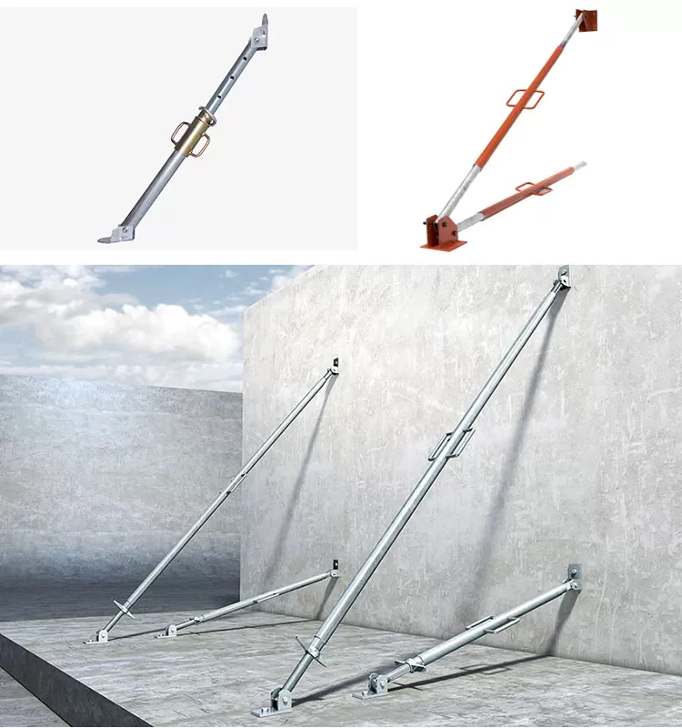
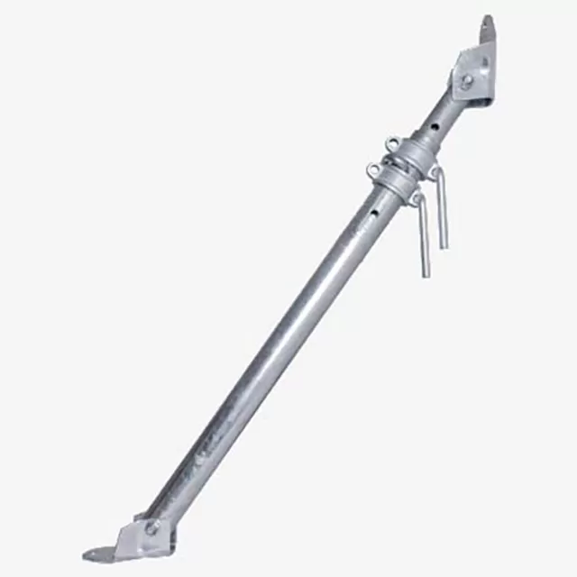
Not recommended. The vertical supports of the floor should be kept as vertical as possible. Significant inclination will reduce the load-bearing capacity and increase the risk of instability. If slope adjustment is required on site, special slope supports or push-pull props should be used instead of vertical supports for the slope roof.
It should not be adjusted at will. The support spacing should be determined based on the aluminum formwork detailing drawing and special construction plan, and should be reviewed in conjunction with slab thickness, floor height, concrete placement method, construction load and early demolition requirements.
Usually simple simultaneous removal is not possible. In the early striking system, the fact that the floor panels are detachable does not mean that the supports are detachable. The retained supports should continue to bear the load according to the plan requirements until the concrete strength and structural conditions meet the requirements for demolition.
You can check whether the jacking and the joist fit well, whether the base is stable, whether the support is shaking, whether the adjusting nut is stressed, whether the adjacent support elevations are consistent, and combined with the flatness of the floor slab and the review results before pouring.
Phone: +8618711321769
Email: alame.vicky@gmail.com
WhatsApp: +8615400055585
Address:No.88, Shuntian Avenue, Xiangyin District, Xiangjiang New District Hunan Province

 EN
EN
 RU
RU
 AR
AR
 ES
ES