
From Zero Foundation to Safe and Efficient Construction
For construction workers who are new to aluminum alloy formwork systems, the large diagonal brace (also known as the diagonal brace rod or adjustable diagonal prop) may be one of the most "troublesome" yet critically important components. The large diagonal brace is the core structural member that ensures the verticality, flatness, and overall stability of aluminum formwork wall panels, and directly affects the quality of concrete forming and construction safety.
This guide uses plain language and intuitive step-by-step instructions to help users with no prior experience quickly master the installation and operation of large diagonal braces.
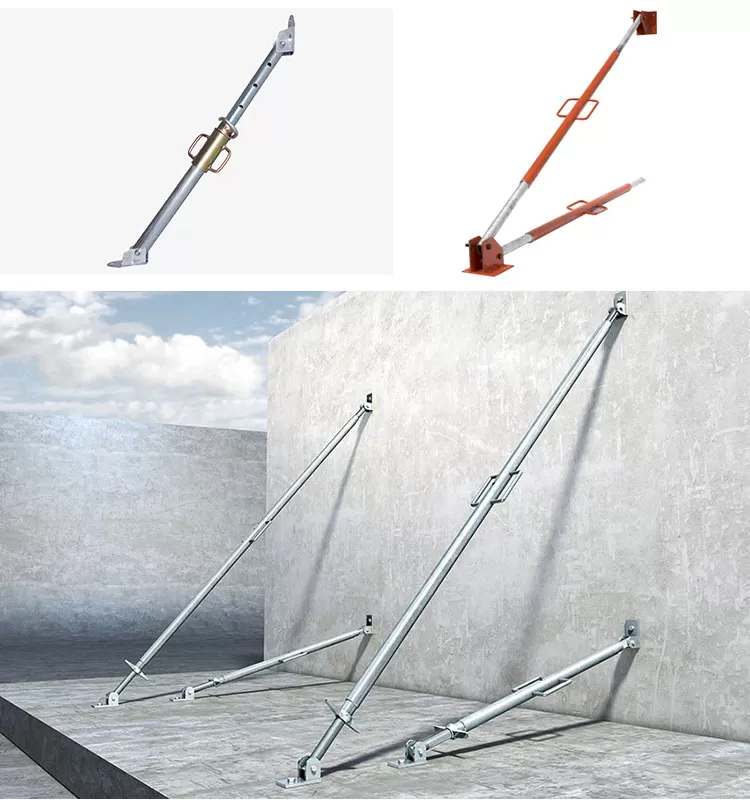
A large diagonal brace is like the guy rope of a tent. Without it, the tent collapses in the wind; without the large diagonal brace, the aluminum formwork wall panel will be pushed out of plumb or even collapse under the enormous lateral pressure during concrete placement.
One end of the large diagonal brace connects to the back waler (or formwork rib plate) of the aluminum formwork wall panel, while the other end is anchored to the floor slab below. By adjusting the length of the diagonal brace, the verticality of the wall panel is corrected while simultaneously resisting the lateral pressure generated during concrete placement.
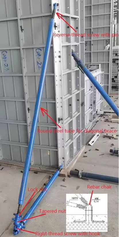
A standard large diagonal brace assembly consists of the following components:
| Component Name | Appearance/Characteristics | Function |
|---|---|---|
| Reverse-thread screw with pin | A screw with a pin welded on one end | Connects to the wall panel edge rib |
| Round steel tube for diagonal brace | Internal threads at both ends, with a through circular hole in the middle | Bears the main load, allows precise adjustment of the brace length |
| Right-thread screw with hook | A screw with a hook welded on one end | Connects to the rebar chair embedded in the floor slab |
| Lock nut | Fits tightly against the round tube | Secures the adjusted length |
| Tapered nut | Tapered tube with internal threads | Prevents the diagonal brace from separating from the rebar chair |
| Rebar chair | U-shaped | Embedded in the floor slab concrete, needs to be exposed above the slab |
Beginner's Tip: Upon receiving the large diagonal brace, manually rotate the adjusting turnbuckle by hand to get a feel for the extension/retraction directions. Typically, turning clockwise shortens the brace and counterclockwise lengthens it (this may vary; verify with the actual component).
Basic Rules:
Common Error: Forgetting to tighten the conical nut, causing the diagonal brace to detach from the rebar chair. Always ensure the conical nut is fully tightened.
Prerequisite:
The aluminum formwork wall panels must be fully assembled and provisionally positioned, and the square hollow section tube (transverse stiffening tube) must already be installed.
Beginner's Technique: If the brace length does not allow the pin to align with the hole, do not force the formwork panel. Instead, adjust the turnbuckle to change the brace length so that the connection bracket aligns naturally.
Following the sequence of "center first, then ends," adjust all diagonal braces to a state where they are "just bearing without applying force." At this point, the wall panel is approximately in position but fine adjustment of verticality has not yet been performed.
This is the most patience-demanding step in the entire construction process.
Typical Procedure (using a single wall panel as an example):
Practical Rhyme:
"Top leans out — extend and push; top leans in — shorten and pull.
One turn, two turns, take it slow; measure and adjust, don’t rush to go."
| Item | Requirement |
|---|---|
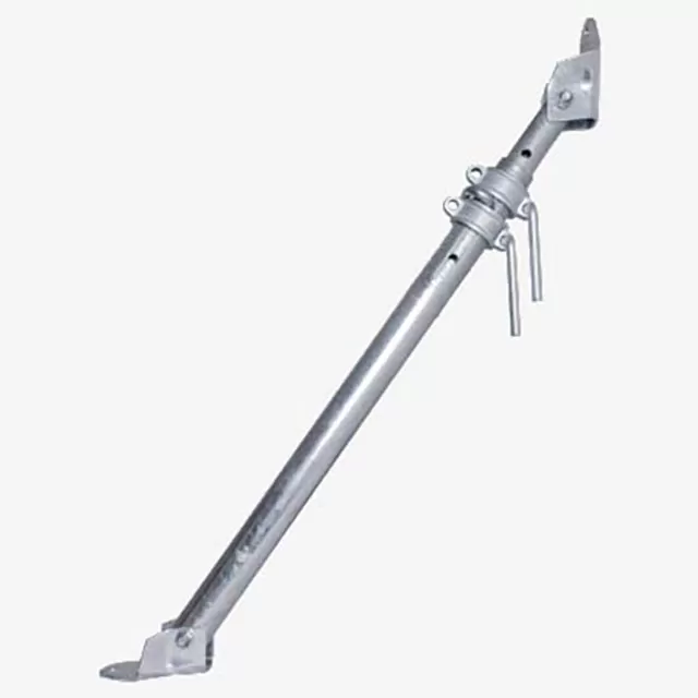
| Installation angle | The angle between the diagonal brace and the ground should ideally be 45°~50°, and must not be < 30° or > 70°. |
| Symmetrical layout | The diagonal braces on both sides of the wall should be arranged symmetrically and in pairs to ensure balanced forces. |
| Pre-pouring inspection | Before pouring concrete, each lock nut must be checked individually to ensure it is tightened. |
| Problem Phenomenon | Possible Cause | Solution |
|---|---|---|
| Wall verticality cannot be adjusted | Insufficient number of diagonal braces or asymmetrical layout | Add more diagonal braces, check if the force is applied only on one side |
| Wall "bulges" after pouring | Spacing between diagonal braces is too large or lock nuts are loose | Densify (add more) diagonal braces, recheck the locking status before pouring |
| Adjusting threaded rod cannot rotate | Threads are rusted or damaged | Clean the threads and apply lubricating oil; replace if severely damaged |
| Overall deviation of the wall | All diagonal braces are bearing force in the same direction | Diagonal braces on both sides should be symmetrically pre-tightened; they cannot all be "pushing" or all "pulling" |
Before installation: Check all components, clear the floor, embed rebar chair
During fixing: Anchor the base, set the angle, arrange symmetrically
During adjustment: Loosen the lock first, rotate slowly, measure and adjust simultaneously
Before placement: Full re-inspection, tighten locking nuts, no movement when shaken
During removal: Wait for strength, relieve load first, then remove base anchors
Keep in mind: Diagonal braces are tough, but safety comes first — never be careless!
Large diagonal braces may look like nothing more than a few iron rods, but within the aluminum formwork system they play the role of the "anchor of stability." For users with no prior experience, do not be intimidated by what may seem like complex operations — follow the four-step cycle of "Measure → Adjust → Lock → Re-inspect" with sufficient patience, and you will be proficient after two or three hands-on sessions.
If you encounter special situations not covered in this guide during actual use (such as non-rectangular wall panels, extra-high floors, or complex site conditions), be sure to consult the project’s technical lead or contact the aluminum formwork manufacturer’s technical support. Never take risks based on experience alone.
Safety is never a minor matter — every brace and every rod bears a thousand kilograms of responsibility.
Phone: +8615400055585
Email: pd13579@qq.com
WhatsApp: +8615400055585
Address:No.88, Shuntian Avenue, Xiangyin District, Xiangjiang New District Hunan Province

 EN
EN
 RU
RU
 AR
AR
 ES
ES