
Casting walls and columns monolithically can reduce construction joints and keep the structural work on one consistent cycle, but it also concentrates the risks into a single pour. Wall panels, column forms, corner forms at wall-to-column junctions, flat ties or tie rods, walers, and push-pull props must work together to resist the lateral pressure of fresh concrete. One missing component or break in the load path can cause bulging, grout leakage, incorrect wall thickness, distorted column corners, or even localized instability.
When a wall and column aluminum formwork system is used, the project team should provide wall thicknesses, column sections, floor-to-floor height, concrete properties, placing equipment, and pour-zone arrangement during the inquiry and detailing stages. The supplier can then prepare the formwork layout and recommended bracing details, while the project team determines the final bracing and casting parameters in accordance with local codes, the approved method statement, and site conditions.
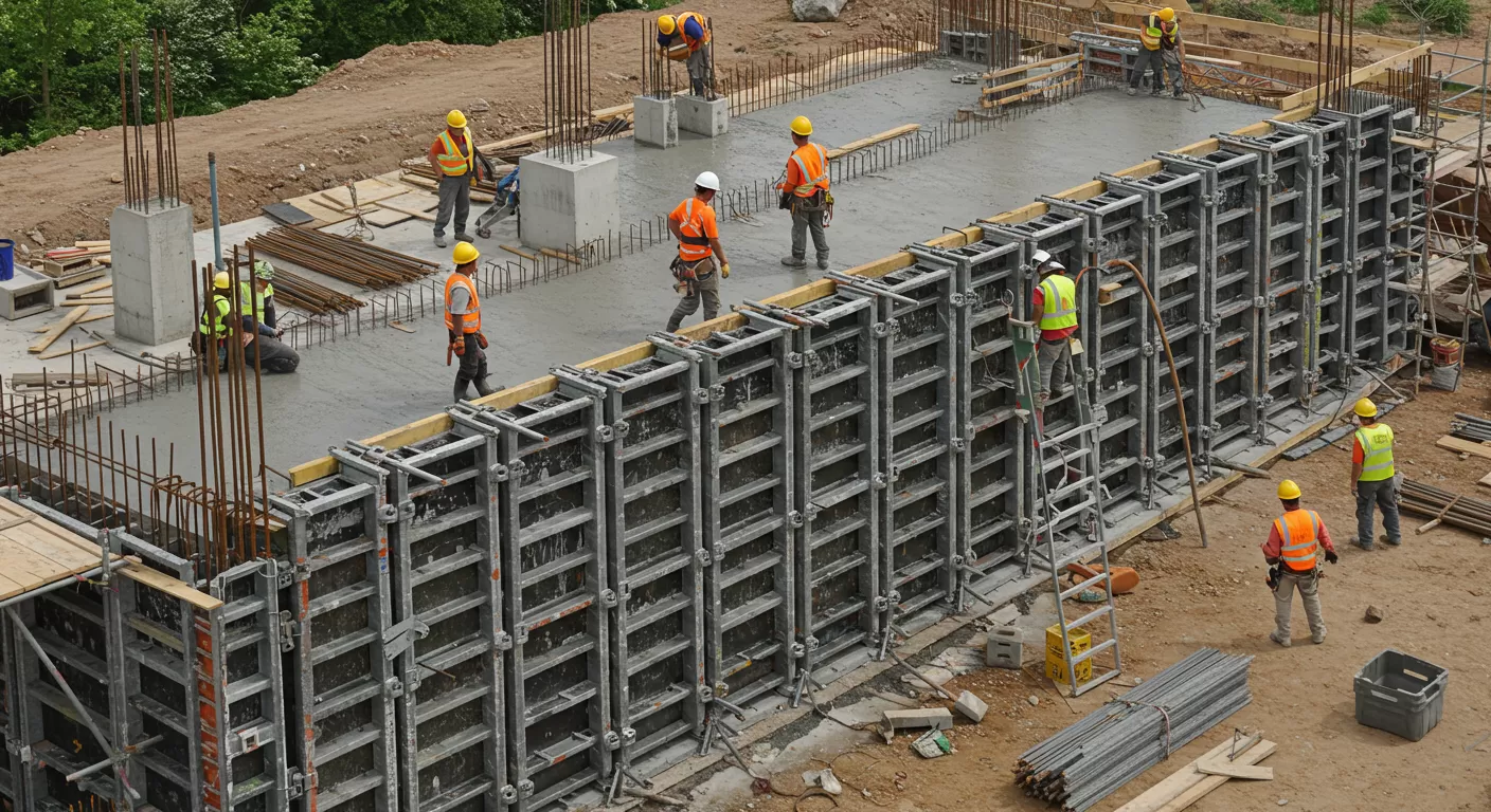
Monolithic casting is not simply a matter of closing the wall and column forms at the same time. Before work begins, the project technical team should confirm the structural drawings, construction-joint locations, concrete strength grades, wall and column sections, reinforcement congestion, and pumping conditions. The following situations require particular review:
If the project method statement does not yet define the casting sequence, lift arrangement, discharge points, and formwork monitoring responsibilities, the pour should not begin solely on the crew's experience.
Wall and column aluminum formwork can be installed in the sequence of setting out, inner forms, junction forms, outer forms, connection and bracing, and final alignment. The specific actions include:
Do not lock all large wall panels first and then force the column corner forms into the remaining space. Temporary supports must not be removed before a junction is closed. At wall-to-column connections, verify corner-form orientation, hole positions, and waler connections before final tightening. These steps should be coordinated with the wider aluminum formwork installation process.
Three problems commonly occur at wall-to-column junctions: panel holes do not align, walers are interrupted, or bracing is asymmetrical on the two sides. Start the inspection at the four column corners and work outward into the adjoining wall sections. Confirm that corner forms fit closely, all pins and wedges are installed, flat ties or tie components match the wall thickness, and walers connect the junction and main panel faces into one assembly. A dependable pin, wedge, and tie system is essential at these locations.
If an adjoining wall panel and column form are at different levels or the joint is too wide, check panel numbers, control lines, and fabrication dimensions first. Do not close the joint by heavy hammering, enlarging holes, or omitting connectors. If a panel must be modified, record the component number and junction location, obtain technical approval, and revise the formwork layout for the same junction on subsequent floors.
The lateral pressure of fresh concrete on formwork is affected by casting height and rate, concrete unit weight and flowability, temperature, setting time, and vibration method. Highly flowable concrete, rapid continuous discharge, and prolonged concentrated vibration all create more demanding loading conditions. Design pressures and component spacing must be determined from the approved project method statement and applicable codes.
Site control must maintain four load paths at the same time:
A break in any one load path must not be compensated for temporarily with another type of accessory. Missing ties, for example, cannot be addressed only by adding push-pull props, and discontinuous walers cannot be replaced by installing more pins. This is also why proper aluminum formwork accessories matter to system performance.
Before casting, the method statement should define pump-line positions, discharge points, movement direction, lift thickness, casting rate, and the person responsible for vibration. Execution should generally remain symmetrical, layered, and continuous without being excessively fast, so that the concrete level in one column or short wall section does not rise rapidly above surrounding areas. Fixed rule-of-thumb values must not replace project calculations and the approved method statement.
The following site controls can be used:
If a wedge loosens, a waler moves, the formwork makes an unusual sound, a joint suddenly leaks grout, or verticality changes noticeably, stop concrete discharge in the affected area immediately in accordance with the project emergency procedure and notify the technical, safety, and casting leads. No one should enter an area where unstable formwork could overturn or suffer a blowout in an attempt to brace it without proper controls.
The response has four steps: first isolate the risk area and assess the concrete level and formwork condition; have authorized personnel approve pressure relief, additional bracing, or other measures; reinspect after rectification; and record the location, casting stage, accessory condition, and cause. The original casting rate must not resume until reinspection is complete.
| Risk Location | Key Inspection Points | What to Monitor During Casting | Closure Records |
|---|---|---|---|
| Wall-to-column junction | Corner forms, hole positions, and waler continuity | Joints, offsets, and junction movement | Junction photographs and remeasurement records |
| Column corners and wall ends | Pins and wedges, ties, and joint sealing | Grout leakage, unusual sounds, and frame deformation | Rectification notice and signed reinspection |
| Both sides of openings | Short wall piers, wall returns, and symmetrical bracing | Opening deformation and one-sided movement | Dimension checks and post-stripping results |
| Wall and column bases | Setting out, cleanliness, and base-joint treatment | Grout loss and bulging at the base | Before-and-after casting photographs |
| High walls or large columns | Method-statement parameters, bearing points, and casting route | Concrete level rise and condition of walers and push-pull props | Formwork monitoring record and incident response form |
After stripping, inspect more than surface flatness. Remeasure wall thickness, column section, verticality, offsets at wall-to-column junctions, integrity of column corners, and opening dimensions. Grout leakage points indicate joint or sealing problems; localized bulging may point to inadequate ties or walers; and distorted column corners require a review of corner-form closure, concrete discharge, and vibration.
Every problem must feed into the next floor: update the junction drawing, provide missing accessories, adjust crew actions, and inspect all identical junctions. Repairing only the concrete surface without changing the installation and casting method does not close the loop. This review supports the accuracy needed for plaster-free concrete.
Risk control in monolithic wall-and-column casting depends on keeping the form-closing sequence, the bracing load paths, and the concrete placement rate aligned. Install the wall-to-column junctions correctly first, ensure continuous load transfer through pins and wedges, ties, walers, and push-pull props, and then control discharge and vibration in accordance with the approved method statement. Agreeing these requirements with the aluminum formwork supplier in advance and reviewing first-floor acceptance results allows monolithic casting to improve efficiency instead of concentrating problems into one pour.
Phone: +8618711321769
Email: alame.vicky@gmail.com
WhatsApp: +8615400055585
Address:No.88, Shuntian Avenue, Xiangyin District, Xiangjiang New District Hunan Province

 EN
EN
 RU
RU
 AR
AR
 ES
ES