
Stairs are one of the easiest places for visible quality problems to show up in an aluminum formwork system. The flatness of walls, columns, beams, and slabs can often be controlled through large-area correction. But once stair treads vary in width, risers are uneven, internal and external corners leak grout, stair side forms bulge, or the joint between upper and lower flights is misaligned, the problems are visible immediately after stripping. They can affect structural measurement, finishing screeds, handrail installation, and the final handover appearance.
For residential, apartment, hotel, and public building projects using an aluminum alloy formwork system, stair forming quality is never just a matter of “putting the formwork in place.” It depends on a full chain of control: shop drawing design, trial assembly and numbering, step dimension review, soffit and side form positioning, pins and wedges, waler reinforcement, push-pull prop correction, concrete placement and vibrating, stripping protection, and turnover maintenance. CIEZN Formwork’s aluminum formwork system covers concrete components such as walls, slabs, beams, columns, stairs, and balconies, so stair formwork should be managed as part of the whole aluminum formwork system if stair dimensions and finish quality are to remain stable.
The quality control target for stair aluminum formwork can be summarized as four accuracies, three straight lines, and two tight joints. The four accuracies are accurate riser height, accurate tread width, accurate flight slope, and accurate landing elevation. The three straight lines are straight step lines, straight stair flight side lines, and straight internal and external corner lines. The two tight joints are tight panel joints and a tight reinforcement system.
During site acceptance, do not only check whether the stripped concrete surface is flat. Structural dimensions, component location, and later finishing requirements should all be reviewed together. Stairwells often involve wall positioning, landing elevation, stair beam nodes, handrail embeds, drip grooves, or anti-slip strip details. If any interface is too far out of tolerance, it can quickly become a repair cost later.
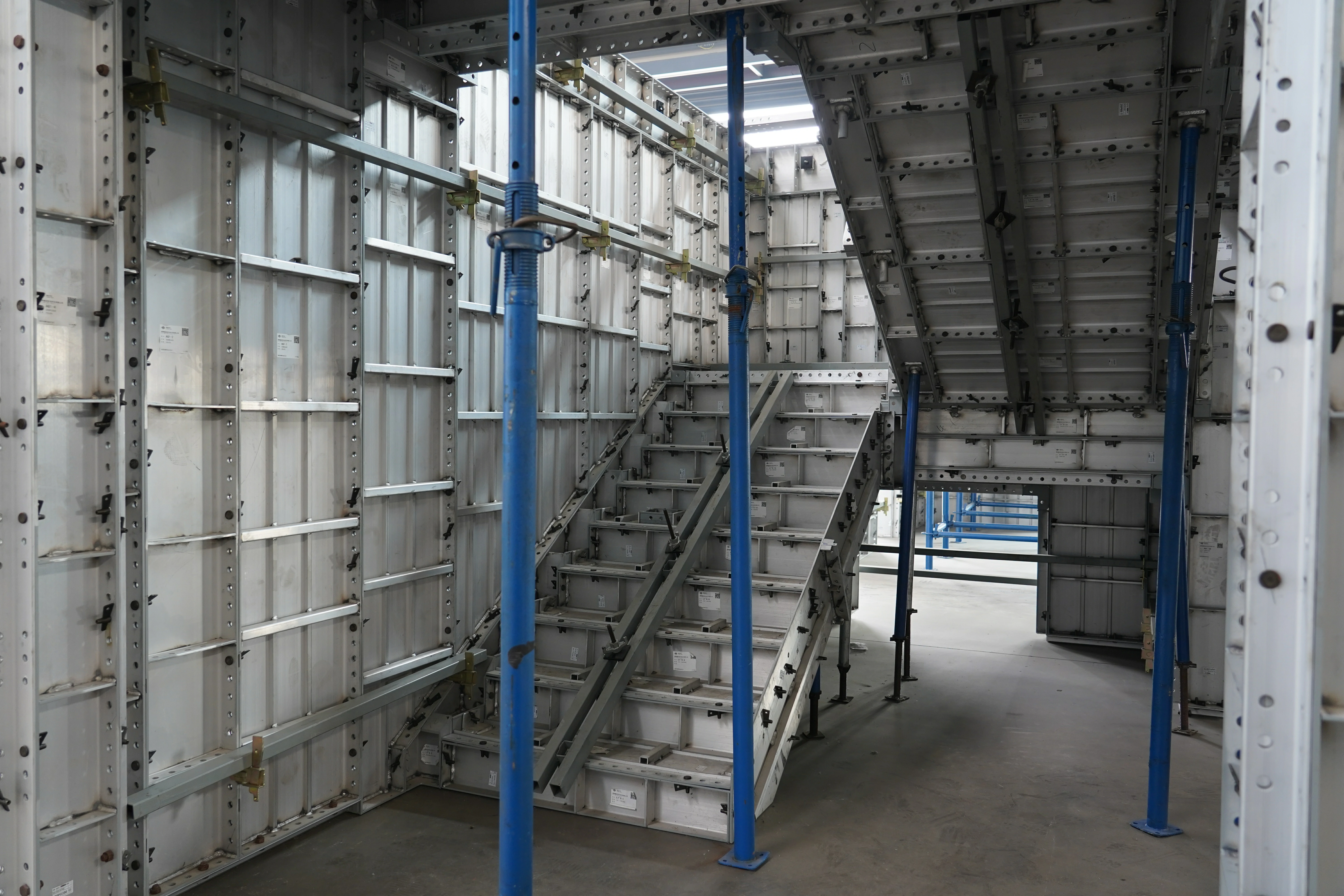
Many stair step deviations are not created during installation; the problem is already embedded during aluminum formwork shop drawing design. The detailed design must clarify structural floor elevation, architectural finished-floor elevation, number of steps, riser height, tread width, landing thickness, stair beam location, wall thickness changes, and clear stairwell dimensions. If the project includes standard floors, non-standard floors, a first-floor lobby, roof level, or machine-room level changes, one stair formwork set should not be applied blindly to all conditions.
Before aluminum formwork fabrication, the architectural drawings, structural drawings, stair details, finishing method, and on-site setting-out conditions should be reviewed together. Pay close attention to the first and last steps because these locations are often affected by floor screed thickness, landing slab thickness, structural sunken areas, thresholds, or finished elevation. If the first and last steps are not checked separately, the middle steps may look uniform after stripping, but the user experience can still be poor because of obvious height differences.
| Control item | Common problem location | Shop drawing and review points |
|---|---|---|
| Riser height | First step, last step, landing connection | Review structural elevation and architectural finished elevation separately to avoid uneven steps after finishing. |
| Tread width | Corner landing, flight starting point | Check architectural clear dimensions, wall position, and tread projection size to prevent step-line displacement. |
| Flight slope | Connection between upper and lower flights, middle of inclined flight | Check the number of steps, horizontal projection of the stair flight, and landing elevation relationship. |
| Landing elevation | Intermediate landing, floor landing | Set out together with beam-slab formwork and wall-column formwork; do not install it as an isolated part. |
| Side form dimension | Wall side, open side | Determine together with wall plumbness, stair beam edge line, and handrail reservation requirements. |
Stair formwork includes soffit panels, side forms, riser panels, end panels, corner forms, connectors, and reinforcement parts. There are many components, and the angular relationships are strong. If every issue is left for floor-by-floor installation, the site can easily run into mismatched holes, reversed riser panels, uneven nosing lines, or temporary patch panels.
A steadier approach is to conduct trial assembly at the factory or before the first floor is built on site. Trial assembly is not only about checking whether the formwork can be joined. It should also check whether the step line is continuous, joints are tight, pin holes work smoothly, panel numbers are clear, and non-standard panels are easy to identify. Numbering should match the shop drawing layout, with clear marks for stair flight direction, upper and lower ends, inside and outside sides, and landing interfaces.
Before stair aluminum formwork installation, the axis lines, wall edge lines, stair flight control lines, landing elevation lines, and first-step starting line must be reviewed. Stairwells are usually narrow, and workers may be tempted to assemble based on the previous floor. But if wall positioning, beam edge lines, or landing elevation are off, later step dimensions will have to be forced into adjustment.
The site should use structural control lines to review stairwell clear width, horizontal projection of the stair flight, landing position, and the connection between upper and lower flights. The soffit support elevation should be adjusted in advance. Do not wait until the step panels are installed and then force the system upward or downward. For non-standard areas such as the first floor, transfer floor, and roof level, increase the frequency of checks.
| Pre-installation check item | Site practice | Quality risk |
|---|---|---|
| Axis and edge lines | Review wall, stair beam, and landing edge lines | Edge-line deviation can reduce clear stair width or shift the side form. |
| Landing elevation | Transfer from a unified elevation control point | Wrong landing elevation can create abnormal height differences at the first or last step. |
| Soffit support | Adjust elevation and slope first, then fix the connections | Soffit settlement can cause uneven riser height and a twisted stair flight surface. |
| Starting line | Confirm the first-step position relative to the landing or floor | An incorrect starting line shifts the whole flight forward or backward. |
| Wall plumbness | Check together with wall formwork correction | A leaning wall can reduce clear stair width and affect side-form joints. |
Stair formwork assembly should not chase speed alone. Riser panels, tread soffit panels, stair side forms, and landing formwork must form a stable closed system. Connectors must be fully inserted, and load-bearing positions need reliable reinforcement. If pins are omitted, wedges are missing, or timber wedges are used to close gaps just to save time, misalignment and grout leakage are very likely during concrete placement.
The step nosing corner is one of the most important appearance points. Nosing corner forms should be straight and free of obvious deformation, and the joints between corner forms, riser panels, and tread panels should fit tightly. The junction between side forms and soffit forms needs special checking to prevent cement paste from escaping through inclined joints and creating pitted sides or weak edges.
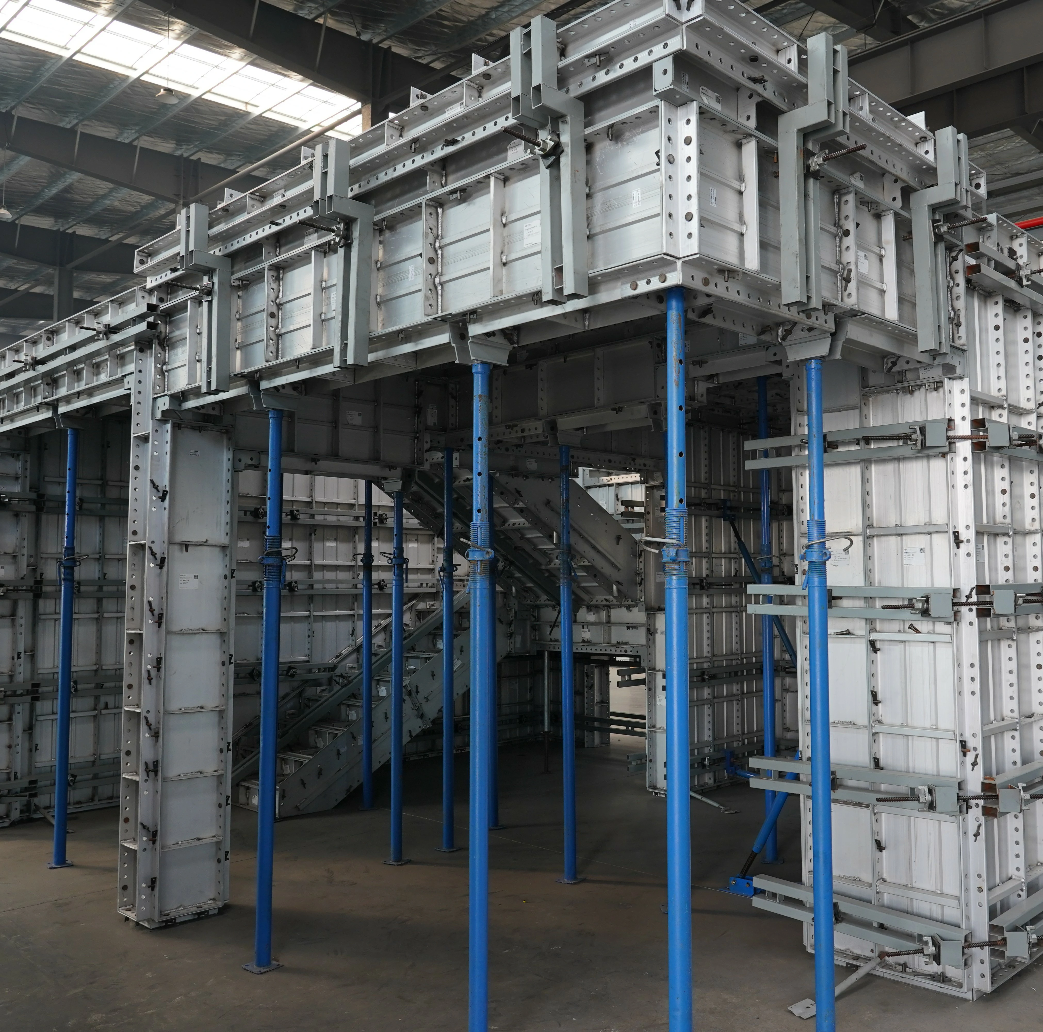
Individual stair formwork panels may not be large, but the geometry is complex. During concrete placement, lateral pressure, vibrating disturbance, and construction load can concentrate on riser panels, side forms, and landing interfaces. If deformation is resisted only by panel-to-panel connectors, common stripped defects include bulged risers, uneven side lines, and misaligned landing joints.
Reinforcement should combine walers, push-pull props, tie connections, and vertical supports according to the formwork system. CIEZN Formwork’s aluminum formwork system includes connection systems, support systems, and reinforcing walers. Stair formwork should use these parts as an integrated stability measure instead of adding temporary reinforcement only after local deformation appears.
| Reinforcement area | Control focus | Common consequence |
|---|---|---|
| Riser panel | Prevent outward bulging and vertical misalignment during concrete placement | Uneven riser height and an uneven riser surface. |
| Stair side form | Control side-line straightness and joint tightness | Side bulging, grout leakage, and curved lines. |
| Landing interface | Keep landing slab, stair beam, and stair flight formwork closed at the same elevation | Interface misalignment and abnormal first or last step. |
| Soffit support | Control load capacity, stability, and settlement | Overall stair flight deflection and slope deviation. |
| Push-pull prop correction | Control plumbness at the connected stair flight and wall areas | Insufficient clear stair width and difficult side-form closure. |
Stair rebar fixing, landing rebar anchorage, handrail embeds, MEP sleeves, and edge-protection embeds all affect the space available for formwork installation. Common site problems include insufficient cover blocks, rebar pressing against riser panels, and embeds conflicting with the formwork. The final “solution” is often to force the formwork to make room, which then causes step dimension deviation.
The right approach is to complete rebar and embed checks before closing the formwork. Rebar should not press directly against aluminum formwork panels, and cover blocks should be stable. Embed locations should match the shop drawings and should not hit corner forms or connection holes. Edge-protection embeds in the stairwell should not interfere with side-form reinforcement. For projects with handrail embeds or decorative line requirements, clearances and finished surfaces should be confirmed earlier.
After stair aluminum formwork is assembled, concrete placement still determines the final forming quality. Stair flights are sloped and steps are dense, so concrete can create local pressure behind riser panels. Honeycombing and pitting can also appear if vibrating is insufficient. During construction, coordinate with the wall, column, beam, and slab placement sequence, control discharge height and placement speed, and avoid concentrated impact on stair side forms or tread panels.
Vibrating should compact the concrete without over-vibrating it. Areas near risers, stair side edges, and landing interfaces need special attention, but the vibrator should not stay against aluminum formwork or rebar for a long time, otherwise formwork movement, grout leakage, or segregation may occur. During placement, assign workers to watch the formwork. Loose wedges, leaking joints, abnormal supports, or formwork movement should be handled immediately.
Step nosing corners are easily damaged after formwork stripping. When removing aluminum formwork, loosen connectors in sequence. Do not pry hard, hammer aggressively, or pull by force, especially at nosing corner panels and side closing panels. If concrete strength is insufficient or stripping is rough, broken nosing edges and missing corners will be very obvious, and later repair will rarely match the clean line of one-time forming.
After stripping, clean residual concrete paste from the formwork surface promptly. Check panel flatness, edge-rib deformation, hole wear, and corner-form notches. Stair finished products should receive temporary protection according to project requirements, so material transport, worker traffic, and secondary structure work do not damage the nosing corners. For panels with many turnover cycles, nosing corner panels and riser panels should be treated as key maintenance items.
| Quality problem | Possible cause | Improvement measure |
|---|---|---|
| Uneven riser height | Landing elevation transfer error, soffit support settlement, or first and last steps not checked separately | Review elevation lines before installation, then recheck soffit supports and step dimensions before concrete placement. |
| Inconsistent tread width | Shop drawing layout error, shifted starting line, or mixed tread panels | Check projection dimensions during detailed design, then install by number and flight direction on site. |
| Bulged riser face | Insufficient connectors, inadequate waler or lateral reinforcement, or concrete placement too fast | Complete pins and wedges, optimize reinforcement points, and control discharge and vibrating. |
| Grout leakage at internal and external corners | Deformed corner forms, loose joints, or insufficient joint sealing | Replace deformed corner forms, check joints during trial assembly, and use joint sealing material when required. |
| Landing interface misalignment | Landing formwork and stair flight formwork not corrected together, or inconsistent support elevation | Set out the landing, stair beam, and stair flight together and inspect them together. |
| Broken edges or missing corners after stripping | Stripping too early, hard prying, or insufficient nosing protection | Strip according to strength requirements, follow the proper stripping sequence, and protect finished corners promptly. |
Common problems include uneven riser heights, inconsistent tread widths, bulged risers, grout leakage at internal and external corners, landing interface misalignment, and broken edges or missing corners after stripping. These problems are usually related to detailed dimensions, setting-out elevation, formwork assembly, reinforcement, and concrete placement and vibrating.
They should be checked at least during shop drawing design, trial assembly, after site installation, and before concrete placement. The first step, last step, landing interface, and non-standard floor stairs need special attention.
It is often caused by deformed corner forms, loose joints, incomplete pins and wedges, insufficient joint sealing, or overly aggressive concrete placement and vibrating. Start by checking panel fit and connection completeness.
Trial assembly is recommended, especially for the first standard floor, non-standard stairs, or projects with complex step details. It helps identify hole, angle, numbering, and joint problems before site installation.
The supplier should provide accurate shop drawing design, clear numbering, reasonable panel division, reinforcement advice, trial assembly checks, and site installation briefing. For stairs, the supplier’s detailing ability and field experience often matter more than the formwork material alone.
The core of stair aluminum formwork quality is not one isolated step. It is continuous control across design, fabrication, trial assembly, setting out, installation, reinforcement, concrete placement, stripping, and turnover maintenance. Step dimensions should be controlled from the drawing and elevation source. Assembly details should start from hole positions, corner forms, connectors, and joints. The reinforcement system must be able to resist lateral pressure and disturbance during concrete placement.
For projects using an aluminum alloy formwork system, stair formwork should be detailed, corrected, and inspected together with wall, slab, beam, column, and balcony formwork. That is how the project reduces later chiseling and repair, while keeping stair structural dimensions, line appearance, and construction efficiency under control.
Phone: +8618711321769
Email: alame.vicky@gmail.com
WhatsApp: +8615400055585
Address:No.88, Shuntian Avenue, Xiangyin District, Xiangjiang New District Hunan Province

 EN
EN
 RU
RU
 AR
AR
 ES
ES