
In an aluminum slab formwork system, slab joists and middle beams are not ordinary crossbars or packing beams. They are key components in the slab load-transfer path. After the slab aluminum formwork panels take the load from fresh concrete, rebar, workers, and site equipment, that load must pass through the joists, middle beams, early striking heads, and steel props to the structure below. If joist selection is wrong, middle beam layout is discontinuous, or prop spacing is too wide, the result may be slab elevation error, soffit deflection, formwork deformation, higher early-striking risk, and poorer concrete finish quality.
For contractors and aluminum formwork buyers, understanding the relationship between joists, middle beams, and prop spacing is the foundation for reliable slab formwork shop drawing design and on-site installation checks.
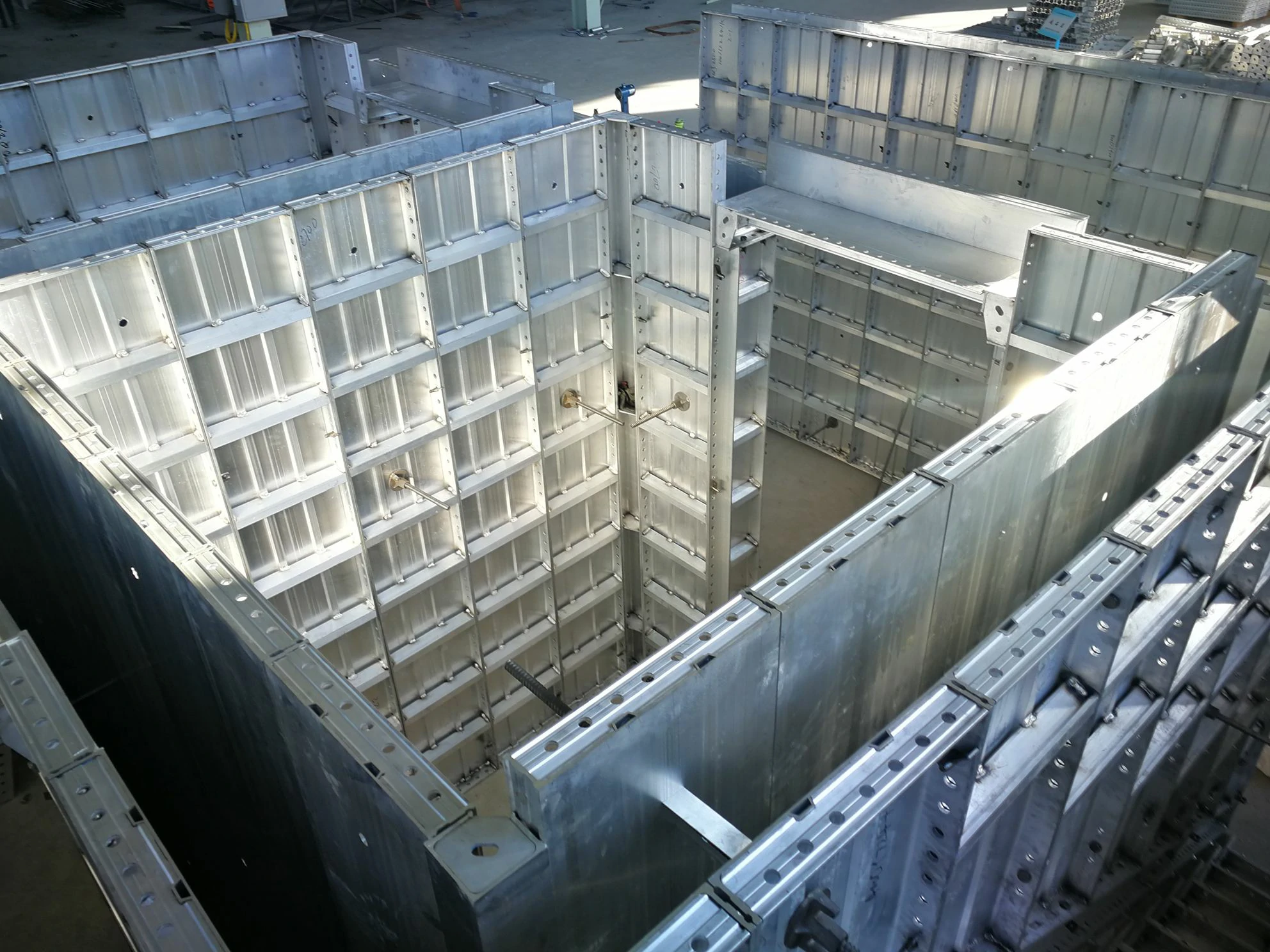
The typical load path of slab aluminum formwork is simple in theory: slab panels carry concrete and construction loads, the load is transferred through slab joists or middle beams to the early striking heads, and then single props or steel props transfer it to the structure below. The job of the joist and middle beam is to collect distributed load from the panels and deliver it to the support nodes, while also controlling slab formwork flatness, stiffness, and stability.
If the team only focuses on slab panel thickness and ignores the joist layout, the system may look complete from above while the load path below is not continuous. This becomes especially important in large bays, around openings, beside beams, in sunken slab areas, kitchens and bathrooms with local level changes, and irregular floor plans. In these areas, the middle beam layout directly affects both formwork safety and turnover efficiency.
| Component name | Main function | On-site understanding |
|---|---|---|
| Formwork Keel / slab joist | Supports slab panels and controls lower-panel stiffness and load transfer. | Usually arranged below panels. It must match the panel module, support nodes, and stripping sequence. |
| Middle Beam | Connects and supports the slab area, acting as the main load-transfer member between panels and the support system. | Usually works with early striking heads and single props, and affects early striking and retained support layout. |
| Quick-Deck Prop Head / early striking head | Connects the middle beam and steel prop, allowing the support to remain during formwork stripping. | In an early striking system, retained supports must not be disturbed while panels are removed. |
| Single Prop / Steel Prop | Provides vertical support and transfers slab load to the structure below. | Prop spacing, plumbness, base bearing, and horizontal stability all need to be checked. |
| Joint Bar | Helps connect slab components and keep formwork assembly continuous. | Weak connections affect joint flatness and overall stiffness. |
Joist selection is not just about whether the part can be installed. It must consider slab thickness, bay size, prop spacing, formwork turnover method, concrete placement speed, construction load, and early striking requirements. In standard residential floors, slab bays and slab thicknesses are relatively stable, so the joist layout can be highly standardized. In basements, podiums, commercial spaces, or irregular structures, joists and middle beams need more detailed shop drawing design based on plan changes.
The key to middle beam layout is to make sure slab loads can be transferred continuously and evenly to the steel props. Middle beams should not be arranged only by asking whether there is enough room to place them. Their layout should be designed together with panel modules, support nodes, early striking head positions, and the stripping sequence.
| Layout principle | Construction point | Risk control |
|---|---|---|
| Match the panel module | The middle beam position should coordinate with slab panel sizes and panel joints. | Avoid excessive edge-panel cantilever or panel ends without reliable support. |
| Match the early striking head | The middle beam should sit on the designed early striking head or support node. | Retained supports must not be disturbed during stripping. |
| Match prop spacing | The middle beam span should be reviewed together with the steel prop layout. | Over-wide prop spacing increases the risk of middle beam deflection and panel deformation. |
| Match irregular areas | Openings, sunken slabs, beam edges, wall edges, and corners should be locally tightened or adjusted. | Prevent local suspension, grout leakage, or uneven slab soffit. |
| Match the stripping sequence | Middle beam layout should support panel removal and retained support logic. | Avoid loosening load-bearing nodes first during stripping. |
Slab prop spacing is not a fixed number. It is determined by slab thickness, formwork system, joist or middle beam specification, prop capacity, concrete placement method, construction load, and early striking requirements. On site, it is not enough to rely on experience and say that one prop should be placed every certain distance. The aluminum formwork shop drawings and project-specific method statement should be the basis.
A prop spacing check usually has three layers. First, whether the capacity of each prop meets the load requirement. Second, whether the middle beam or joist has acceptable deflection and strength at that spacing. Third, whether the overall support system is stable, including horizontal ledgers, couplers, base bearing, and the bearing condition of the lower structure.
Before installation, check the floor axis lines, elevation control lines, slab thickness, opening positions, beam edges, and sunken slab areas. Slab joists, middle beams, early striking heads, and steel props should be installed according to the shop drawing numbers, so components from different zones are not mixed.
In a slab aluminum formwork system, steel props and early striking heads are the main support points for middle beams. Props should be vertical, the bases stable, and the height properly adjusted. Early striking heads should connect reliably with the middle beams. If the props are not adjusted correctly before the middle beams are installed, later elevation adjustment becomes harder.
When installing middle beams and joists, make sure the ends are fully seated, connections are complete, and elevations are consistent. Splices, laps, or joint bars between adjacent middle beams should be installed according to the system requirements. There should be no suspension, misalignment, twisting, or forced fitting.
After the slab panels are laid, check panel joints, pins and wedges, corners, and opening-edge reinforcement. Panels should have full contact with the joists or middle beams. If part of the panel soffit is unsupported, it may sink or create an uneven slab bottom during concrete placement.
Before concrete placement, use a level, laser level, or control line to recheck slab soffit elevation and flatness. Also check steel props, horizontal ledgers, couplers, early striking heads, and middle beam connections to confirm the slab support system is stable and reliable.
CIEZN’s 6061-T6 reusable lightweight aluminum formwork system emphasizes that slab panels can be removed without moving the supports. This advantage depends on the correct configuration of middle beams, early striking heads, and retained supports. During early striking, slab panels can be turned over, but retained supports must not be disturbed.
For that reason, the stripping route must be considered during middle beam layout: which panels are stripped first, which middle beams can be removed, which supports must remain, whether the early striking heads may be hit during stripping, and whether retained supports are clearly marked. If these points are not considered during the shop drawing stage, early stripping on site can quickly become a risky “decide while stripping” process.
| Problem | Possible cause | Recommended solution |
|---|---|---|
| Local slab soffit deflection | Prop spacing is too wide, middle beam span is too long, or panel ends have no reliable support. | Review the joist and middle beam layout. If needed, add props or adjust support nodes. |
| Inconsistent slab elevation | Steel prop heights are uneven, early striking heads are not tight, or middle beams are locally suspended. | Before concrete placement, recheck elevation as a whole and adjust props and middle beams by zones. |
| Retained supports disturbed during stripping | The early striking sequence is unclear, or middle beam and early striking head layout is unreasonable. | Define retained support positions in advance and prohibit loosening load-bearing nodes during stripping. |
| Opening-edge deformation or grout leakage | Joists around the opening are insufficient, edge panels lack support, or pins and wedges are missing. | Review openings, sunken slabs, and beam-edge areas separately. Add support where needed. |
| Support system shaking | Horizontal steel rods or couplers are missing, or prop bases are unstable. | Install horizontal restraints according to the method statement, and check bases and couplers. |
When purchasing slab aluminum formwork, do not focus only on the unit price of panels. What really affects site efficiency and finish quality is whether slab panels, slab joists, middle beams, early striking heads, steel props, joint bars, pins and wedges, horizontal steel rods, swivel couplers, and right-angle couplers are supplied as a compatible set. A complete slab system should also include shop drawings, component numbering, support layout drawings, early striking instructions, and on-site installation guidance.
For overseas projects, provide structural drawings, slab thickness, floor height, beam and slab layout, target construction cycle, concrete placement method, and local worker installation experience before ordering. With that information, the supplier can optimize middle beam layout and prop spacing, reducing secondary modification after the system arrives on site.
Not exactly. A slab joist is more like a secondary load-bearing component that supports slab panels, while a middle beam is usually a more important load-transfer member in the slab system and often works with early striking heads and steel props. Names may vary between manufacturers, so the shop drawings and component numbers should govern.
Not recommended. Prop spacing should be determined by the detailed design and project-specific method statement. Widening it casually increases the risk of middle beam deflection, panel deformation, and slab elevation error.
These areas have irregular formwork assembly and the load path can be interrupted easily. They also include more edge panels and short panels. If joist and prop layout is insufficient, grout leakage, misalignment, deflection, or difficult stripping may occur.
It depends. Which middle beams or panels can be removed, and which supports and nodes must remain, should follow the early striking system design, concrete strength conditions, and the project-specific method statement.
Construction load and stripping sequence are often overlooked. Selection based only on slab thickness is not enough. Pump pipes, placing booms, material stacking, early striking routes, and retained supports must also be considered.
Selecting slab formwork joists and middle beams is, in essence, a balance between slab load transfer and construction turnover efficiency. A reasonable middle beam layout keeps panel loading continuous, support nodes clear, and the early stripping sequence controlled. Reasonable prop spacing helps control slab elevation, soffit flatness, and concrete placement safety. In aluminum formwork projects, joists, middle beams, early striking heads, steel props, horizontal ledgers, and couplers must be designed as one system, not judged as separate accessories.
Phone: +8618711321769
Email: alame.vicky@gmail.com
WhatsApp: +8615400055585
Address:No.88, Shuntian Avenue, Xiangyin District, Xiangjiang New District Hunan Province

 EN
EN
 RU
RU
 AR
AR
 ES
ES